
TM 55-2815-574-24
0072
INSTALLATION - Continued
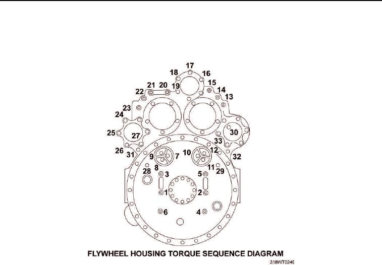
42.
Use torque wrench and a torque sequence diagram (Figure 28) to torque the twenty ninth through thirty third
cap screws to 137 to 147 ft lb (186 to 199 Nm).
Figure 28.
43.
Apply ultra blue sealing compound to flywheel housing (Figure 29, Item 1) and to access cover
(Figure 29, Item 4).
44.
Install new gasket (Figure 29, Item 3) on flywheel housing (Figure 29, Item 1).
45.
Install access cover (Figure 29, Item 4) on flywheel housing (Figure 29, Item 1).
46.
Install cap screw (Figure 29, Item 7) through copper washer (Figure 29, Item 8), access cover
(Figure 29, Item 4) and gasket (Figure 29, Item 3).
47.
Install five cap screws (Figure 29, Item 6) and lockwashers (Figure 29, Item 5).
48.
Use torque wrench and socket set to torque cap screws (Figure 29, Items 6 and 7) to 300 to 360 in-lb
(34 to 41 Nm).
49.
Use torque wrench and socket set to torque cap screws (Figure 29, Items 2 and 1) to 300 to 360 in-lb
(34 to 41 Nm).