
TM 55-2815-574-24
0073
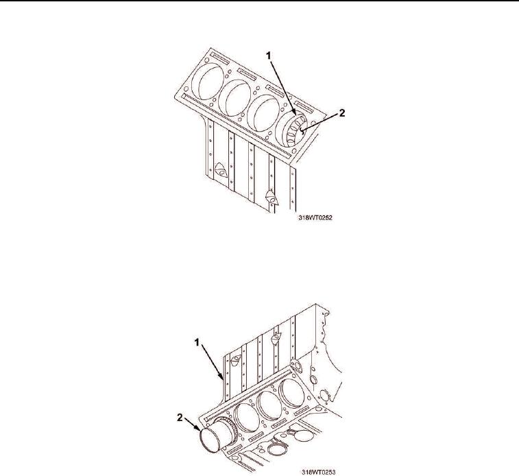
REMOVAL - Continued
Figure 2. Piston and Air Inlet Ports.
8.
Continue rotation of crankshaft and push piston and liner assembly (Figure 3, Item 2) out of block
(Figure 3, Item 1).
Figure 3. Piston and Liner Assembly.