
TM 55-2815-574-24
0073
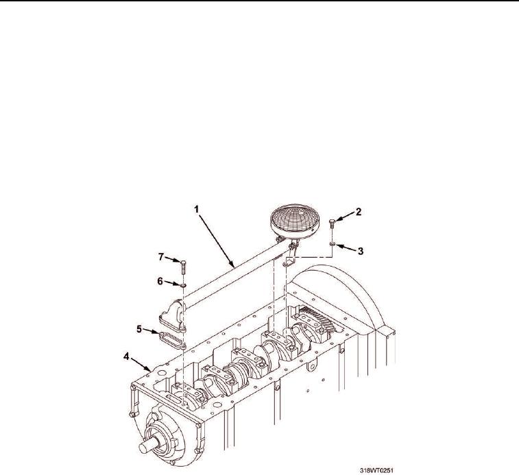
REMOVAL
1.
Rotate engine (Figure 1, Item 4) so bottom side is up.
2.
Remove oil distribution inlet tube and screen assembly (Figure 1, Item 1) as follows:
a.
Remove two cap screws (Figure 1, Item 7) and lockwashers (Figure 1, Item 6) from oil distribution inlet
tube and screen assembly (Figure 1, Item 1). Discard lockwashers.
b.
Remove two cap screws (Figure 1, Item 2) and washers (Figure 1, Item 3) from oil distribution inlet
tube and screen assembly (Figure 1, Item 1).
c.
Remove oil distribution inlet tube and screen (Figure 1, Item 1) as an assembly.
d.
Remove and discard gasket (Figure 1, Item 5).
3.
Rotate engine (Figure 1, Item 4) so top side is up.
Figure 1. Oil Distribution Inlet Tube and Screen Assembly Removal.
4.
Lower piston (Figure 2, Item 2) to just above air inlet ports (Figure 2, Item 1).
5.
Insert liner puller into cylinder liner air inlet ports (Figure 2, Item 1).
6.
Raise piston (Figure 2, Item 2) until it makes contact with liner puller tool and pushes liner puller tool to top
of air inlet port (Figure 2, Item 1).
7.
Rotate engine (Figure 1, Item 4) so bottom side is up.