
TM 55-2815-574-24
0073
INSTALLATION - Continued
5.
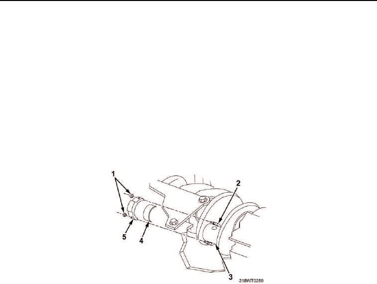
Coat connecting rod bearings (Figure 9, Item 4) with lubricating oil.
6.
Install upper half of bearing (Figure 9, Item 4) onto connecting rod (Figure 9, Item 2).
7.
One soldier inserts piston (Figure 8, Item 1) and liner assembly.
8.
Position crankshaft journal (Figure 9, Item 3) at the bottom of its stroke.
9.
Lubricate crankshaft journal (Figure 9, Item 3) with lubricating oil.
10.
Second soldier guides connecting rod (Figure 9, Item 2) onto crankshaft journal (Figure 9, Item 3).
11.
Install lower half of bearing (Figure 9, Item 4) in connecting rod cap (Figure 9, Item 5).
12.
Install connecting rod cap (Figure 9, Item 5) onto connecting rod (Figure 9, Item 2).
13.
Install two hex nuts (Figure 9, Item 1).
14.
Using torque wrench, torque hex nuts (Figure 9, Item 1) to 70 ft-lb (95 Nm).
Figure 9. Connecting Rod Bearings Installation.
15.
Install holddown clamps to hold liner into place.
16.
Repeat Steps 1 through 14 to install remaining seven piston and liner assemblies.