
TM 55-2815-574-24
0073
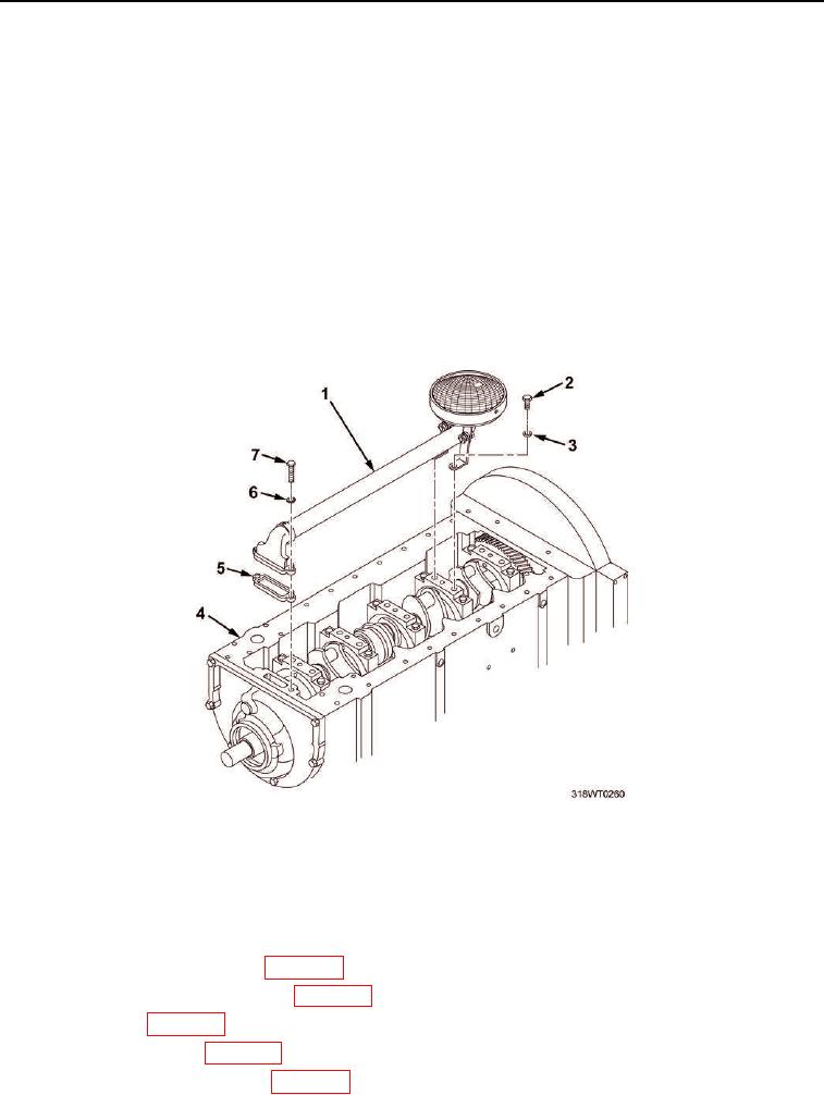
INSTALLATION - Continued
17.
Rotate engine (Figure 10, Item 4) so that bottom is up.
18.
Install the oil distribution inlet tube and screen assembly (Figure 10, Item 1) as follows:
a.
Install new gasket (Figure 10, Item 5).
b.
Position oil distribution inlet tube and screen assembly (Figure 10, Item 1) on engine
(Figure 10, Item 4).
c.
Install two washers (Figure 10, Item 3) and cap screws (Figure 10, Item 2) in oil distribution inlet tube
and screen assembly (Figure 10, Item 1).
d.
Tighten cap screws (Figure 10, Item 2).
e.
Install two new lockwashers (Figure 10, Item 6) and cap screws (Figure 10, Item 7) in oil distribution
inlet tube and screen assembly (Figure 10, Item 1).
f.
Tighten cap screws (Figure 10, Item 7).
Figure 10. Oil Distribution Inlet Tube and Screen Hardware Installation.
END OF TASK
FOLLOW-ON MAINTENANCE
1.
Install oil pressure relief valve (WP 0125).
2.
Install oil pressure regulator valve (WP 0123).
3.
Install oil pan (WP 0127).
4.
Install cylinder heads (WP 0047).
5.
Install fuel injector control tube (WP 0086).