
TM 55-2815-574-24
0032
REMOVAL
1.
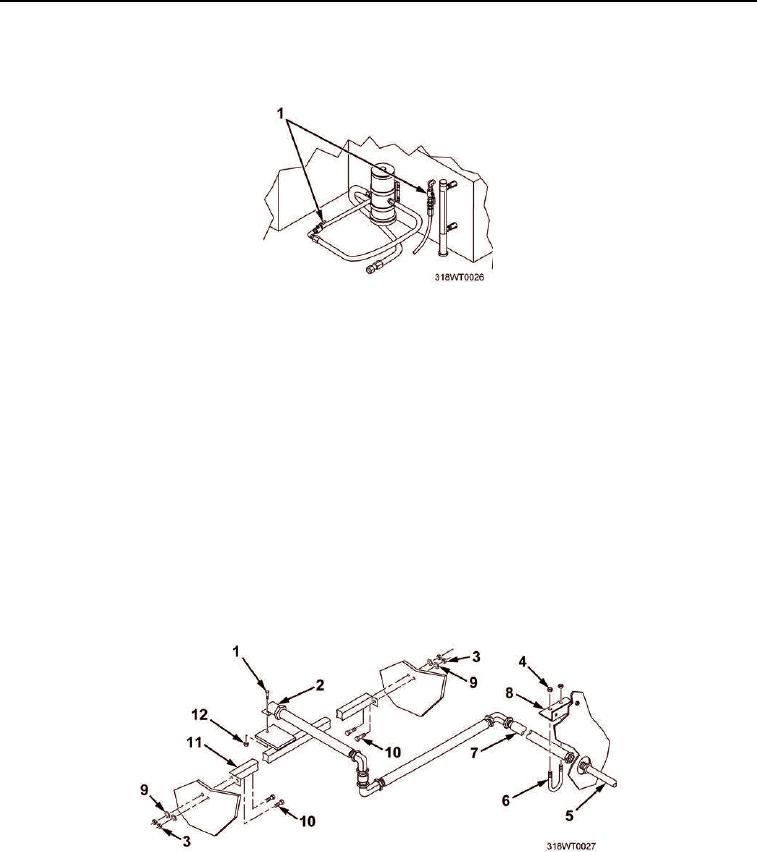
Verify fuel supply and return valves (Figure 1, Item 1) are closed.
Figure 1. Fuel Supply and Return Valves Removal.
2.
Remove nut (Figure 2, Item 12) and bolt (Figure 2, Item 1) securing fire suppression trip mechanism
solenoid (Figure 2, Item 2) to its mount, located above the engine.
3.
Using a pipe wrench, disconnect pipe coupling (Figure 2, Item 5) for fire suppression CO2 supply line
(Figure 2, Item 7) that feeds fire suppression trip mechanism solenoid (Figure 2, Item 2) near the propulsion
module frame cross-member support bracket (Figure 2, Item 8).
4.
Remove two nuts (Figure 2, Item 4) and U-joint bolt (Figure 2, Item 6) supporting CO2 supply line
(Figure 2, Item 7) to the propulsion module frame cross-member support bracket (Figure 2, Item 8).
5.
Remove CO2 supply line (Figure 2, Item 7) with attached fire suppression trip mechanism solenoid
(Figure 2, Item 2).
6.
Remove four nuts (Figure 2, Item 3), flat washers (Figure 2, Item 9), and bolts (Figure 2, Item 10) securing
fire suppression trip mechanism solenoid's cross-module bracket (Figure 2, Item 11) to propulsion module
longitudinal frame.
7.
Remove cross-module bracket (Figure 2, Item 11).
Figure 2. Fire Suppression System Removal.