
TM 55-2815-574-24
0032
REMOVAL - Continued
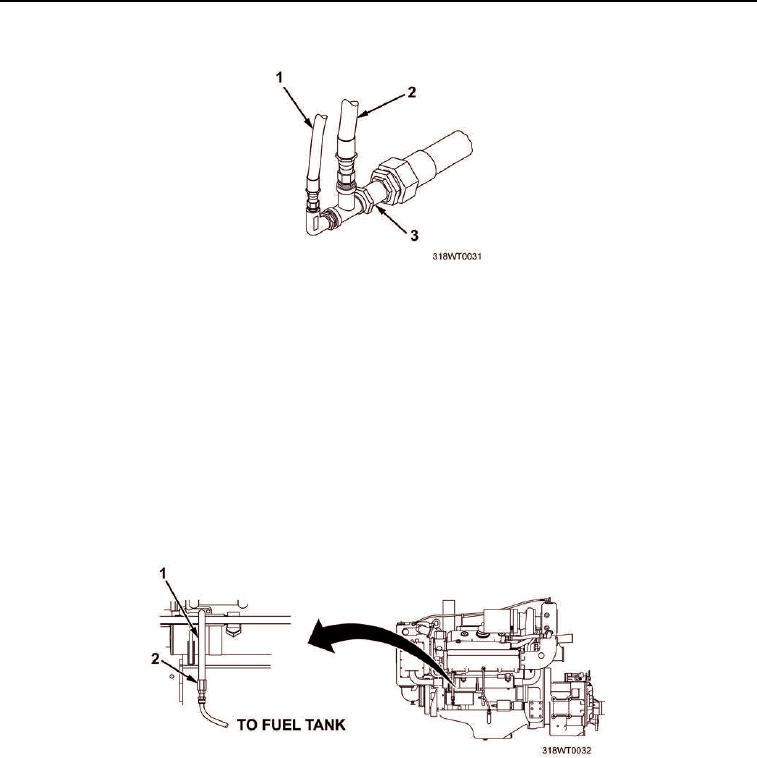
Figure 6. Fuel Supply Check Valve Removal.
17.
Position drain pan beneath fuel pump return line (Figure 7, Item 1) coupling, located on the forward port side
of engine.
18.
Remove fuel pump return line (Figure 7, Item 1) from main fuel return line (Figure 7, Item 2).
NOTE
The main fuel return line will remain in the bilge and will not interfere with engine removal.
19.
Secure fuel pump return line (Figure 7, Item 1) to engine with twine.
20.
Remove drain pan and dispose of contents in accordance with local procedures.
21.
Clean up spilled fluids with spill clean-up kit and dispose of spill clean-up kit in accordance with local
procedure.
Figure 7. Fuel Pump Return Line Removal.
22.
Tag and disconnect two marine gear shifting solenoid electrical connectors (Figure 8, Item 1) from two
marine gear shifting solenoids (Figure 8, Item 2) and secure to engine with twine.