
TM 55-2815-574-24
0032
REMOVAL - Continued
WARNING
Hazardous fumes may be present. Wear protective clothing and goggles while handling.
Failure to comply may result in personnel injury or death.
8.
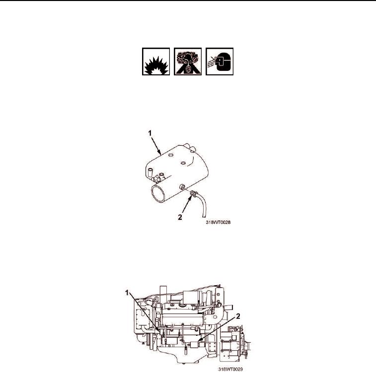
Disconnect cold pack starting supply line (Figure 3, Item 2) from starboard side of air inlet housing
(Figure 3, Item 1) and secure outboard with twine.
Figure 3. Air Inlet Housing Removal.
9.
Tag and disconnect two red battery power leads from starter solenoid (Figure 4, Item 2) and alternator
(Figure 4, Item 1).
Figure 4. Starter Solenoid and Alternator Removal.
10.
Remove inline tiedown straps, pull leads off engine, and secure leads outboard with twine. Discard tiedown
straps.
11.
Inside engine junction box A4 (Figure 5, Item 1), tag and disconnect all terminal leads associated with main
engine electrical wire bundle (Figure 5, Item 2)
12.
Once the wire bundle (Figure 5, Item 2) is isolated from engine junction box A4 (Figure 5, Item 1), remove
tiedown straps, and coil and secure wire bundle on top of engine with twine. Discard tiedown straps.