
TM 55-2815-574-24
0041
INSTALLATION - Continued
3.
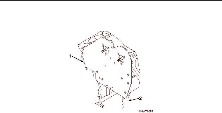
Install front block plate (Figure 4, Item 1) on engine block (Figure 4, Item 2).
Figure 4. Engine Block.
4.
Install two hex head screws (Figure 5, Item 5) and new lockwashers (Figure 5, Item 4) in front block plate
(Figure 5, Item 2) into engine block (Figure 5, Item 1) finger tight.
5.
Install five hex head screws (Figure 5, Item 6) and new lockwashers (Figure 5, Item 3) in front block plate
(Figure 5, Item 2) finger tight.
NOTE
The smaller right hand cam bearing shall be used as a pilot while aligning the front block
plate on the engine block.
6.
Install two cam bearings (Figure 5, Item 7) into front block plate (Figure 5, Item 2).
7.
Install six cap screws (Figure 5, Item 9) and new lockwashers (Figure 5, Item 8) securing cam bearings
(Figure 5, Item 7) to front block plate (Figure 5, Item 2).
8.
Using torque wrench and socket set, torque six cap screws (Figure 5, Item 9) to 480 in-lb (54 Nm).
9.
Using torque wrench and socket set, torque hex head screws (Figure 5, Item 6) to 420 in-lb (47 Nm).
10.
Using torque wrench, torque hex head screws (Figure 5, Item 5) to 75 ft-lb (102 Nm).