
TM 55-2815-574-24
0041
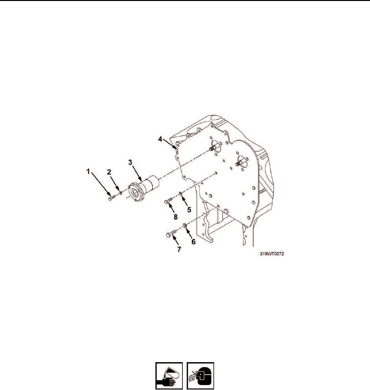
REMOVAL
1.
Remove six cap screws (Figure 1, Item 1) and lockwashers (Figure 1, Item 2) securing two cam bearings
(Figure 1, Item 3) to front block plate (Figure 1, Item 4). Discard lockwashers.
2.
Remove two cam bearings (Figure 1, Item 3) from front block plate (Figure 1, Item 4).
3.
Remove five hex head screws (Figure 1, Item 8) and lockwashers (Figure 1, Item 5) from front block plate
(Figure 1, Item 4). Discard lockwashers.
4.
Remove two hex head screws (Figure 1, Item 7) and lockwashers (Figure 1, Item 6) from front block plate
(Figure 1, Item 4). Discard lockwashers.
Figure 1. Cam Bearings.
5.
Remove front block plate (Figure 2, Item 4) and gaskets (Figure 2, Items 1 and 3) from engine block
(Figure 2, Item 2). Discard gaskets.
END OF TASK
INSTALLATION
WARNING
Sealing compound may cause irritation to the eyes or skin. Use in well-ventilated area.
Wear protective goggles and clothing. In case sealing compound comes in contact with:
Eyes, flush immediately with water.
Skin, wash with soap and water.
Failure to comply may result in personnel injury.
1.
Coat front block plate (Figure 2, Item 4) and engine block (Figure 2, Item 2) with sealing compound.