
TM 55-2815-574-24
0040
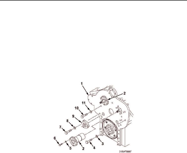
REMOVAL
NOTE
Retain lockwashers for installation.
1.
Remove hex head screw (Figure 1, Item 7), special washer (Figure 1, Item 8), and dummy bearing
(Figure 1, Item 9) from rear end plate (Figure 1, Item 1).
2.
Remove six cap screws (Figure 1, Item 6) and lockwashers (Figure 1, Item 5) from two cam bearings
(Figure 1, Item 2).
3.
Remove two cam bearings (Figure 1, Item 2) from rear end plate (Figure 1, Item 1).
4.
Remove hex head screw (Figure 1, Item 4) and lockwasher (Figure 1, Item 3) from rear end plate
(Figure 1, Item 1).
5.
Remove four hex head screws (Figure 1, Item 10) and lockwashers (Figure 1, Item 11) from rear end plate
(Figure 1, Item 1).
Figure 1. Rear End Plate.
6.
Remove rear end plate (Figure 2, Item 3) and gasket (Figure 2, Item 2) from engine block (Figure 2, Item 1).
Discard gasket.
END OF TASK