
TM 55-2815-574-24
0047
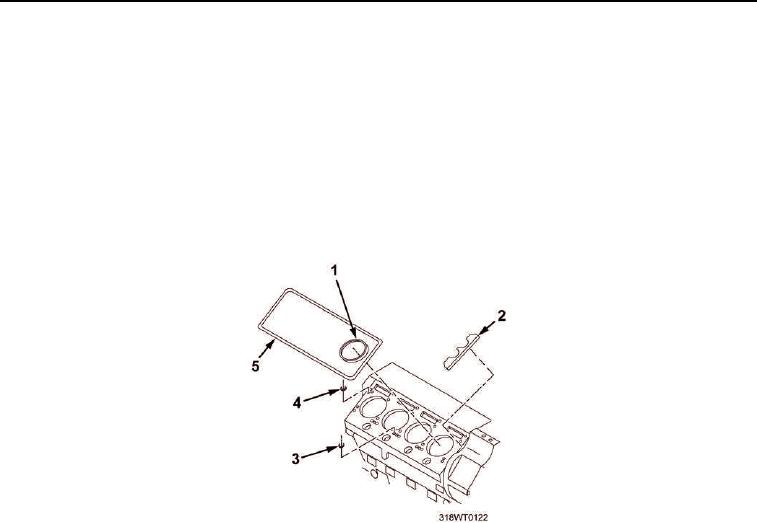
REMOVAL - Continued
NOTE
Compression gaskets are color coded. Make note of color before removing gaskets.
17.
Record color and remove four cylinder head compression gaskets (Figure 3, Item 1).
18.
Remove cylinder block seal strip gasket (Figure 3, Item 5).
19.
Remove two support shims (Figure 3, Item 2).
20.
Remove oil seal (Figure 3, Item 4).
21.
Remove 16 water seals (Figure 3, Item 3).
Figure 3. Cylinder Head Gasket Removal.
END OF TASK
INSTALLATION
NOTE
New compression gaskets are color coded red, black or no paint on outside
diameter to identify thickness. Only one color coded gasket should be used under
any one cylinder head.
An optional design, with no paint identification and of one thickness, compression
gasket may be used. It may be intermixed on an engine under the same head with
the current no paint compression gasket.
1.
Install four cylinder head compression gaskets (Figure 4, Item 1) of the same color removed.
2.
Remove adhesive paper and install support shims (Figure 4, Item 2).
3.
Position support shim (Figure 4, Item 2), scallop at rear of cylinder block (Figure 4, Item 12), near oil supply
hole.
4.
Install oil seal (Figure 4, Item 14) with color side facing away from cylinders.
5.
Install 16 water seals (Figure 4, Item 11).
6.
Install seal strip gasket (Figure 4, Item 15).