
TM 55-2815-574-24
0047
INSTALLATION - Continued
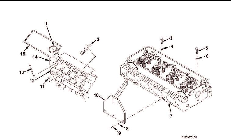
Figure 4. Cylinder Block and Cylinder Head.
NOTE
Failure to torque in sequence or repeat sequence may result in compression leaks when
engine is placed in operation.
19.
Using torque wrench, torque cylinder head bolts (Figure 5, Items 1 and 2) in number order to 50 ft-lb
(67.8 Nm).
NOTE
Upon reaching final torque, steady pressure for two or three seconds must be held to allow
gaskets to seat properly.
20.
Using torque wrench, torque bolts (Figure 5, Items 1 and 2) to 100 ft-lb (135.6 Nm).
21.
Repeat torque sequence to 100 ft-lb (135.6 Nm) to ensure first bolts torqued did not lose clamp load.
22.
Mark position of each cylinder bolt head (Figure 5, Items 1 and 2) in relation to cylinder head profile face.
23.
Tighten each cylinder head bolt (Figure 5, Items 1 and 2) in sequence, 90 degrees with one pull of the
wrench, from marked position.