
TM 55-2815-574-24
0047
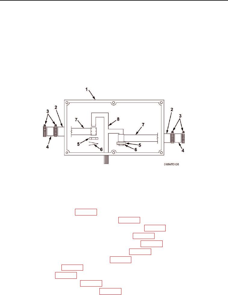
INSTALLATION - Continued
26.
Install fuel rods (Figure 7, Item 7).
a.
Insert ends of fuel rods (Figure 7, Item 7) through governor housing (Figure 7, Item 1) and through fuel
rod cover tubes (Figure 7, Item 2).
b.
Install ends of fuel rods (Figure 7, Item 7) on governor shaft assembly (Figure 7, Item 8).
c.
Install two washers (Figure 7, Item 5) and connecting pins (Figure 7, Item 6) on governor shaft
assembly (Figure 7, Item 8).
27.
Slide two fuel rod cover tube hoses (Figure 7, Item 4) down on cover tubes (Figure 7, Item 2) attached to
cylinder heads.
28.
Tighten four hose clamps (Figure 7, Item 3).
Figure 7. Fuel Rod Installation.
END OF TASK
FOLLOW-ON MAINTENANCE
1.
Install fuel injector control tube (WP 0086).
2.
Install cylinder head poppet valve rocker arm covers (WP 0044).
3.
Install fresh water cooling system starboard water outlet manifold (WP 0146).
4.
Install fresh water cooling system port water outlet manifold (WP 0145).
5.
Install fresh water cooling system starboard thermostat housing (WP 0140).
6.
Install fresh water cooling system port thermostat housing (WP 0141).
7.
Install fresh water cooling system bypass hoses (WP 0143).
8.
Install exhaust manifold (WP 0157).
9.
Install turbochargers (WP 0114).
10.
Install air inlet collector assembly (WP 0104).
11.
Install crankcase breather limiter assembly (WP 0106).
12.
Install engine hatch (TM 55-1925-205-23).