
TM 55-2815-574-24
0048
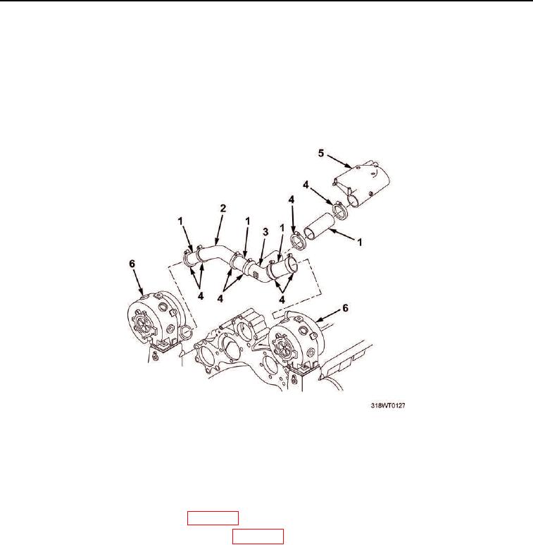
INSTALLATION - Continued
10.
Install the Y-duct (Figure 3, Item 3), angle tube (Figure 3, Item 2) and four hoses (Figure 3, Item 1) between
turbochargers (Figure 3, Item 6) and air inlet housing (Figure 3, Item 5).
11.
Install eight band clamps (Figure 3, Item 4) on Y-duct (Figure 3, Item 3), angle tube (Figure 3, Item 2) and
four hoses (Figure 3, Item 1) between the turbochargers (Figure 3, Item 6) and air inlet housing
(Figure 3, Item 5).
12.
Tighten eight band clamps (Figure 3, Item 4).
Figure 3. Turbocharger Air Hoses Installation.
END OF TASK
FOLLOW-ON MAINTENANCE
1.
Install air inlet collector assembly (WP 0104).
2.
Install crankcase breather limiter assembly (WP 0106).
3.
Install engine hatch (TM 55-1925-205-23).
4.
Install operator`s cab (TM 55-1925-205-23).
5.
Install intake plenum (TM 55-1925-205-23).
6.
Install main mast navigation assembly (TM 55-1925-205-23).
7.
Install SINCGARS antenna (TM 11-5820-890-10-8).