
TM 55-2815-574-24
0048
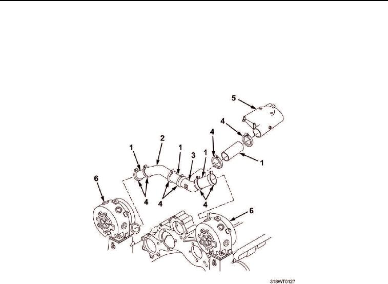
REMOVAL
1.
Loosen eight band clamps (Figure 1, Item 4) from Y-duct (Figure 1, Item 3), angle tube (Figure 1, Item 2),
and four hoses (Figure 1, Item 1) between the turbochargers (Figure 1, Item 6) and air inlet housing
(Figure 1, Item 5).
2.
Remove Y-duct (Figure 1, Item 3), angle tube (Figure 1, Item 2), and four hoses (Figure 1, Item 1) from
between turbochargers (Figure 1, Item 6) and air inlet housing (Figure 1, Item 5).
Figure 1. Turbocharger Air Hoses Removal.
3.
Remove two hex nuts (Figure 2, Item 12) and lockwashers (Figure 2, Item 13) from capscrews
(Figure 2, Item 3).
4.
Remove band bracket (Figure 2, Item 2) from mounting bracket (Figure 2, Item 4).
5.
Remove two hex nuts (Figure 2, Item 11) and lockwashers (Figure 2, Item 10) from capscrews
(Figure 2, Item 5).
6.
Remove mounting bracket (Figure 2, Item 4).
7.
Remove two capscrews (Figure 2, Item 7) and lockwashers (Figure 2, Item 6) from lifting bracket
(Figure 2, Item 8).
8.
Remove lifting bracket (Figure 2, Item 8). Discard lifting bracket.
9.
Remove gasket (Figure 2, Item 9) from engine (Figure 2, Item 1). Discard gasket.
END OF TASK
INSTALLATION
1.
Position new gasket (Figure 2, Item 9) on engine (Figure 2, Item 1).
2.
Position new lifting bracket (Figure 2, Item 8) on engine (Figure 2, Item 1).