
TM 55-2815-574-24
0059
REMOVAL - Continued
5.
Remove fuel manifold (WP 0051).
6.
Remove fuel injectors (WP 0091).
7.
Remove cam followers (WP 0053).
WARNING
Handling heavily weighted objects can cause bodily injury. Do not lift materials or
equipment over 50 lb (23 kg) without using appropriate material handling equipment.
Ensure proper lifting techniques are followed when removing or installing heavy
components. Use assistant(s) and/or suitable lifting device when lifting heavy parts of
components. Failure to comply may result in personnel injury, death, and/or damage
to equipment.
8.
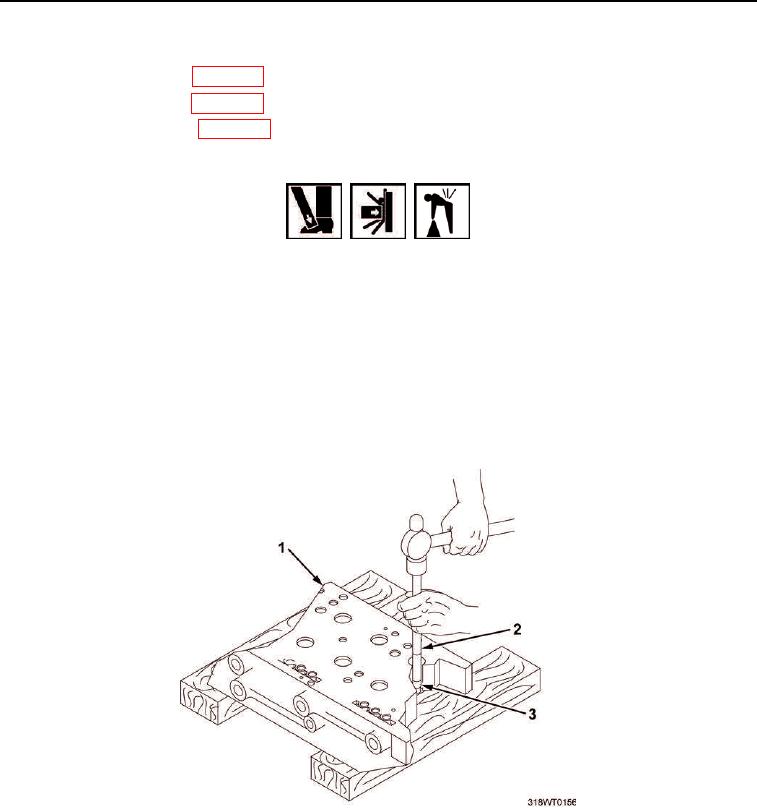
Place cylinder head (Figure 2, Item 1), bottom side up, on two wood wedges.
9.
10.
Using valve guide driver (Figure 2, Item 2), drive valve guide (Figure 2, Item 3) out of cylinder head
(Figure 2, Item 1). Discard valve guide.
Figure 2. Cylinder Head.
END OF TASK