
TM 55-2815-574-24
0059
INSTALLATION
WARNING
Keep hands and fingers away from arbor press moving parts. Failure to comply may result
in personnel injury.
1.
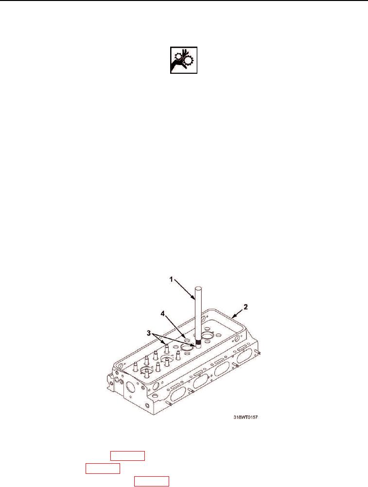
Place cylinder head (Figure 3, Item 2), right side up, on arbor press.
2.
Insert internally threaded end of new valve guide (Figure 3, Item 3) in valve guide installing tool
(Figure 3, Item 1).
CAUTION
Do not use valve guides or valve guide tool, when the tool is installed in cylinder head, to
handle or turn over the cylinder head. Damage to valve guides and/or tool will occur.
Failure to comply may result in damage to equipment.
3.
Position valve guide (Figure 3, Item 3) squarely in valve guide bore (Figure 3, Item 4) and gently press valve
guide installation tool (Figure 3, Item 1) to start valve guide (Figure 3, Item 3) in place.
4.
Press valve guide (Figure 3, Item 3) until valve guide installation tool (Figure 3, Item 1) contacts cylinder
head (Figure 3, Item 2).
5.
Remove valve guide installation tool (Figure 3, Item 1).
6.
Using machinists rule, verify height of valve guide (Figure 3, Item 3) above cylinder head (Figure 3, Item 2)
is 0.670 to 0.710 in. (1.70 to 1.80 cm) above cylinder head.
7.
Remove cylinder head (Figure 3, Item 2) from arbor press.
Figure 3. Valve Guide Installation.
8.
Install fuel system injectors (WP 0091).
9.
Install fuel manifold (WP 0051).
10.
Install cylinder head cam followers (WP 0053).