
TM 55-2815-574-24
0075
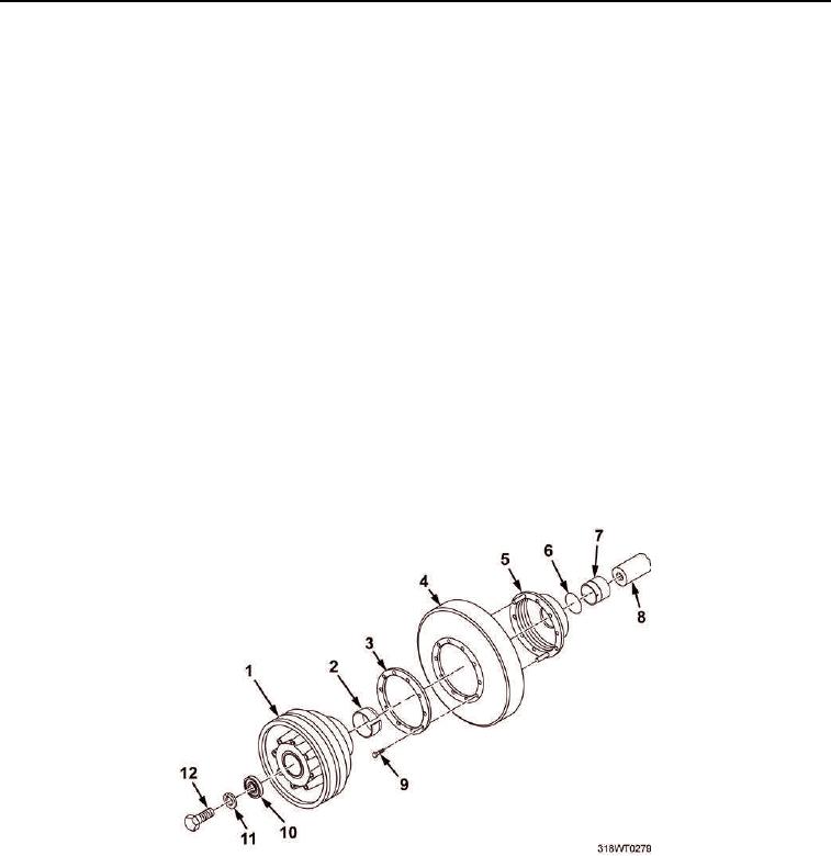
REMOVAL
1.
Remove crankshaft pulley retaining bolt (Figure 1, Item 12), lockwasher (Figure 1, Item 11), and
washer (Figure 1, Item 10).
2.
Using puller, remove crankshaft pulley (Figure 1, Item 1).
3.
Install crankshaft pulley retaining bolt (Figure 1, Item 12) in crankshaft (Figure 1, Item 8).
4.
Using puller, remove scuff plate (Figure 1, Item 3), vibration dampener (Figure 1, Item 4),
hub (Figure 1, Item 5), and outer cone (Figure 1, Item 2) as an assembly, until outer cone is loose on
crankshaft (Figure 1, Item 8).
5.
Using punch, remove outer cone (Figure 1, Item 2) out of vibration dampener (Figure 1, Item 4).
6.
Remove puller and pull outer cone (Figure 1, Item 2) from crankshaft (Figure 1, Item 8).
7.
Remove scuff plate (Figure 1, Item 3), vibration dampener (Figure 1, Item 4), and hub (Figure 1, Item 5)
as an assembly from crankshaft (Figure 1, Item 8).
8.
Remove inner cone (Figure 1, Item 7) from crankshaft (Figure 1, Item 8).
9.
Remove nitrile seal ring (Figure 1, Item 6) from inner cone (Figure 1, Item 7). Discard nitrile seal ring.
10.
Remove eight bolts (Figure 1, Item 9) from scuff plate (Figure 1, Item 3).
11.
Remove scuff plate (Figure 1, Item 3) and hub (Figure 1, Item 5) from vibration dampener (Figure 1, Item 4).
Discard vibration dampener.
12.
Remove crankshaft pulley retaining bolt (Figure 1, Item 12) from crankshaft (Figure 1, Item 8).
Figure 1. Vibration Dampener Removal.
END OF TASK