
TM 55-2815-574-24
0075
INSTALLATION
WARNING
Do not allow any oil to drip onto deck. Failure to comply may result in injury to personnel.
NOTE
All parts on front of crankshaft must be positioned easily without any noticeable
1.
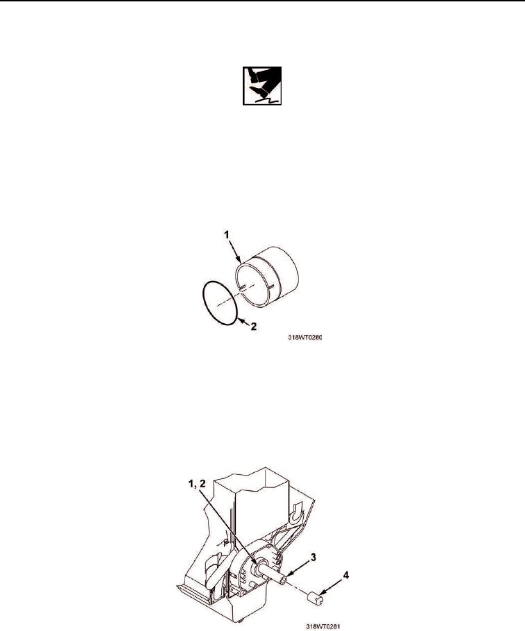
Lubricate new nitrile seal ring (Figure 2, Item 2) with engine lubricating oil.
2.
Install nitrile seal ring (Figure 2, Item 2) in groove inside inner cone (Figure 2, Item 1).
Figure 2. Inner Cone Installation.
NOTE
Tapered end of inner cone must point toward front end of crankshaft.
3.
Slide inner cone (Figure 3, Item 4) over end of crankshaft (Figure 3, Item 3) through
oil seal (Figure 3, Item 1) and up against oil pump drive hub (Figure 3, Item 2).
Figure 3. Oil Pump Drive Hub Installation.