
TM 55-2815-574-24
0075
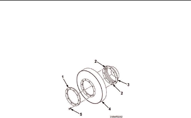
INSTALLATION - Continued
4.
Align new vibration dampener (Figure 4, Item 4) with dowel pins (Figure 4, Item 2) on hub (Figure 4, Item 3)
and assemble new vibration dampener and hub.
5.
Place scuff plate (Figure 4, Item 1) over dowel pins (Figure 4, Item 2) against vibration
dampener (Figure 4, Item 4).
6.
Install eight bolts (Figure 4, Item 5).
7.
Using torque wrench, torque vibration dampener/hub assembly bolts (Figure 4, Item 5) to 75 to 85 ft-lb
(102 to 115 Nm).
Figure 4. Vibration Dampener/Hub Assembly.
8.
Position vibration dampener and hub assembly (Figure 5, Item 3) over end of crankshaft (Figure 5, Item 4),
with long end of hub facing inner cone (Figure 5, Item 5).
9.
Position outer cone (Figure 5, Item 2) over end of crankshaft (Figure 5, Item 4) with tapered end of outer
cone pointing toward vibration dampener and hub assembly (Figure 5, Item 3).
10.
Install pulley (Figure 5, Item 1) on crankshaft (Figure 5, Item 4).
11.
Install washer (Figure 5, Item 6), lockwasher, (Figure 5, Item 7), and crankshaft pulley retaining
bolt (Figure 5, Item 8) to crankshaft (Figure 5, Item 4).
12.
Tighten crankshaft pulley bolt (Figure 5, Item 8) as follows:
a.
Using torque wrench, torque crankshaft pulley retaining bolt (Figure 5, Item 8) to 180 ft-lb (244 Nm).
b.
Using a dead blow hammer, strike end of crankshaft pulley bolt (Figure 5, Item 8) a sharp blow.
c.
Using torque wrench, torque crankshaft pulley retaining bolt (Figure 5, Item 8) to 300 ft-lb (407 Nm).
d.
Using a dead blow hammer, strike end of crankshaft pulley bolt (Figure 5, Item 8) a sharp blow.
e.
Using torque wrench, torque crankshaft pulley bolt (Figure 5, Item 8) to 290 to 310 ft-lb
(393 to 420 Nm).