
TM 55-2815-574-24
0080
REMOVAL FUEL TUBES - Continued
3.
Verify fuel supply and return valves (Figure 2, Item 1) are closed.
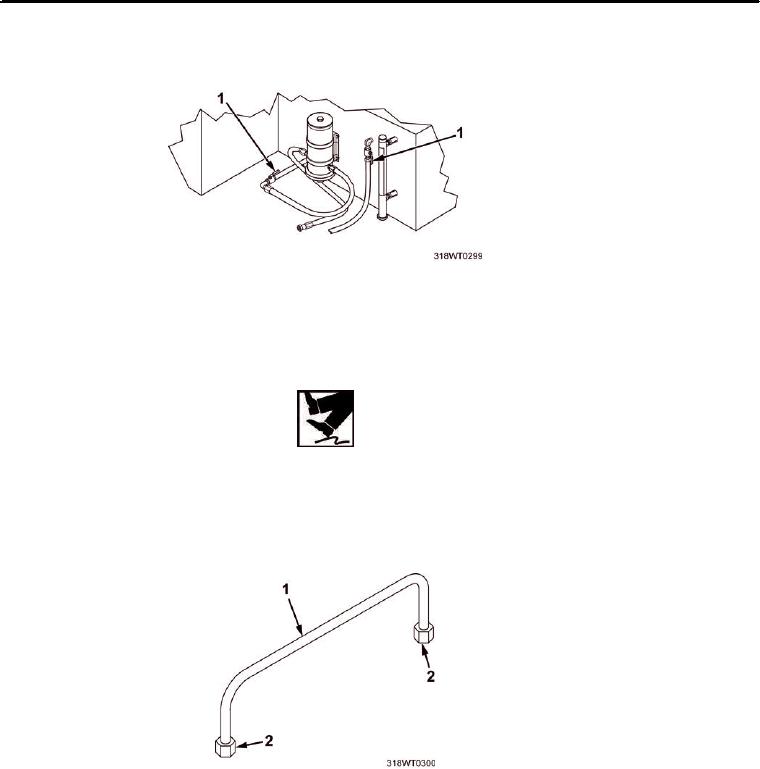
Figure 2. Fuel Supply and Return Valves.
4.
Position drain pan under tube (Figure 3, Item 1) being removed.
WARNING
Do not allow any oil to drip onto deck. Failure to comply may result in injury to personnel.
5.
Loosen B-nut (Figure 3, Item 2) on each end of tube (Figure 3, Item 1).
6.
Remove tube (Figure 3, Item 1), drain residual fuel into drain pan. Discard tube (Figure 3, Item 1).
7.
Remove drain pan and dispose of contents in accordance with local procedures.
Figure 3. Fuel Tube.
END OF TASK
INSTALLATION FUEL TUBES
1.
Install tube (Figure 3, Item 1) onto fittings.
2.
Tighten B-nut (Figure 3, Item 2) at each end of tube (Figure 3, Item 1).
3.
Remove LO/TO from A3 breaker switch.