
TM 55-2815-574-24
0080
INSTALLATION FUEL TUBES - Continued
4.
Clean up spilled fluid with a spill clean-up kit and dispose of spill clean-up kit waste in accordance with local
procedures.
5.
Start engine (TM 55-1925-205-10).
6.
Check fuel lines for leaks.
7.
Shut down engine (TM 55-1925-205-10).
END OF TASK
REMOVAL FUEL RUBBER HOSES
1.
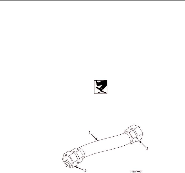
Position drain pan under hose (Figure 4, Item 1) being removed for draining residual fuel from hose.
WARNING
Do not allow any oil to drip onto deck. Failure to comply may result in injury to personnel.
2.
Loosen B-nut (Figure 4, Item 2) at each end of hose (Figure 4, Item 1).
3.
Remove hose (Figure 4, Item 1), drain residual fuel into drain pan and discard hose (Figure 4, Item 1).
4.
Remove drain pan and dispose of drain pan in accordance with local procedures.
Figure 4. Fuel Hose.
END OF TASK
INSTALLATION FUEL RUBBER HOSES
1.
Install hose (Figure 4, Item 1) on fittings.
CAUTION
Do not overtighten B-nut or damage to fitting threads will occur.
2.
Tighten B-nut (Figure 4, Item 2) on each end of hose (Figure 4, Item 1).
0080-4