
TM 55-2815-574-24
0081
REMOVAL - Continued
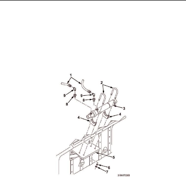
8.
Position second drain pan under fuel cooler (Figure 4, Item 3).
9.
Remove two fuel lines (Figure 4, Item 1) from elbows (Figure 4, Item 9) and allow fuel to drain
into drain pan.
10.
Remove two elbows (Figure 4, Item 9) from bushings (Figure 4, Item 8).
11.
Remove two bushings (Figure 4, Item 8) from fuel cooler (Figure 4, Item 3).
12.
Remove four hex nuts (Figure 4, Item 7) and lockwashers (Figure 4, Item 6) from two clamps
(Figure 4, Item 2).
13.
Remove two clamps (Figure 4, Item 4) from fuel cooler (Figure 4, Item 3).
14.
Remove fuel cooler (Figure 4, Item 3) from bracket (Figure 4, Item 5) and discard.
Figure 4. Fuel Cooler Removal.
15.
Remove two drain pans and dispose of contents in accordance with local procedures.
END OF TASK