
TM 55-2815-574-24
0081
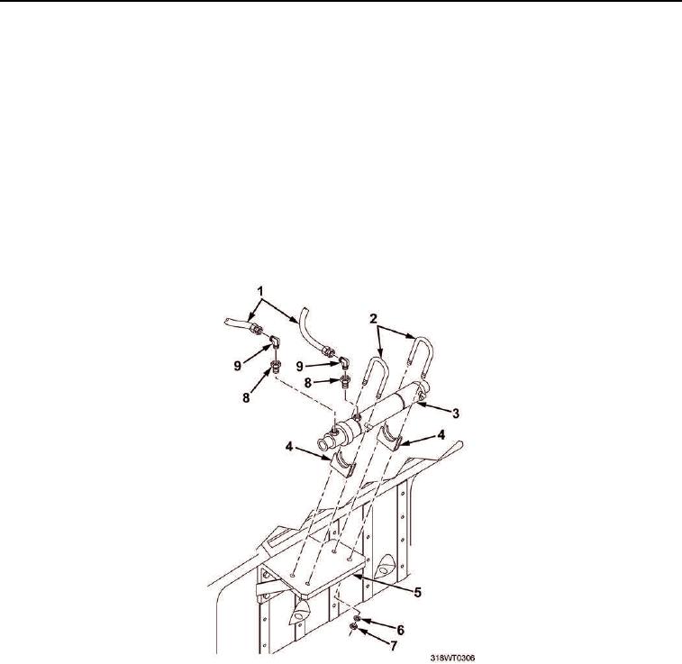
INSTALLATION
1.
Install two clamps (Figure 5, Item 4) on new fuel cooler (Figure 5, Item 3).
2.
Position new fuel cooler (Figure 5, Item 3) on bracket (Figure 5, Item 5).
3.
Install four hex nuts (Figure 5, Item 7) and lockwashers (Figure 5, Item 6) on clamps (Figure 5, Item 2).
4.
Tighten hex nuts (Figure 5, Item 7).
5.
Wrap bushing (Figure 5, Item 8) threads with antiseizing tape.
6.
Install two bushings (Figure 5, Item 8) on fuel cooler (Figure 5, Item 3).
7.
Wrap elbows (Figure 5, Item 9) threads with antiseizing tape.
8.
Install two elbows (Figure 5, Item 9) on bushings (Figure 5, Item 8).
9.
Install two fuel lines (Figure 5, Item 1) on elbows (Figure 5, Item 9).
Figure 5. Fuel Cooler Installation.