
TM 55-2815-574-24
0081
INSTALLATION - Continued
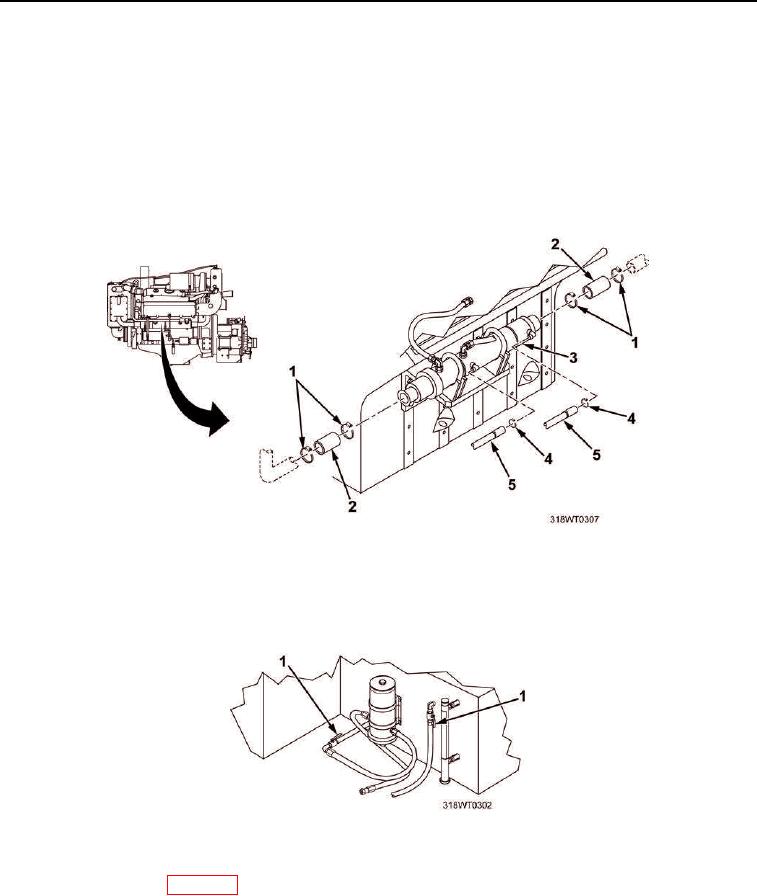
10.
Install two fresh water coolant hoses (Figure 6, Item 5) on fuel cooler (Figure 6, Item 3).
11.
Install two clamps (Figure 6, Item 4) on fresh water coolant hoses (Figure 6, Item 5).
12.
Tighten clamps (Figure 6, Item 4).
13.
Install four clamps (Figure 6, Item 1) on two hoses (Figure 6, Item 2).
14.
Install two hoses (Figure 6, Item 2) on fuel cooler (Figure 6, Item 3).
15.
Tighten clamps (Figure 6, Item 1).
Figure 6. Fuel Cooler Hoses Installation.
16.
Service fresh water cooling system (TM 55-1925-205-10).
17.
Open fuel supply valves (Figure 7, Item 1).
Figure 7. Fuel Supply Return Valves.
18.
Prime fuel system (WP 0078).
19.
Start engine (TM 55-1925-205-10).
20.
Check fuel cooler (Figure 6, Item 3) for leaks.
21.
Shut engine down (TM 55-1925-205-10).
22.
Service fresh water cooling system (TM 55-1925-205-10).