
TM 55-2815-574-24
0085
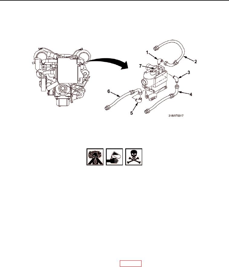
INSTALLATION - Continued
23.
Install fuel line (Figure 4, Item 2) on elbow (Figure 4, Item 1).
24.
Tighten fuel line (Figure 4, Item 2).
Figure 4. Fuel Adapter Block Lines Installation.
WARNING
Accidental or intentional introduction of liquid contaminants into the environment
may result in a violation of state, federal, and military regulations. Refer to local
environmental office for information concerning storage, use, and disposal of
these liquids. Failure to comply may cause damage to environment and health
of personnel. Seek medical attention in the event of injury.
Fuel/solvent/oil is slippery and may cause falls. Wipe up spillage immediately with
rags. Dispose of materials in accordance with local hazardous waste disposal
procedures. Failure to comply may result in personnel injury or death and/or
damage to equipment.
25.
Clean up spilled fluid with a spill clean-up kit and dispose of spill clean-up kit waste in accordance with local
procedure.
END OF TASK
FOLLOW-ON MAINTENANCE
1.
Install auto shutdown system fuel oil pressure switch (WP 0173).
2.
Perform operational check of diesel engine (TM 55-1925-205-10).
END OF TASK
END OF WORK PACKAGE