
TM 55-2815-574-24
0086
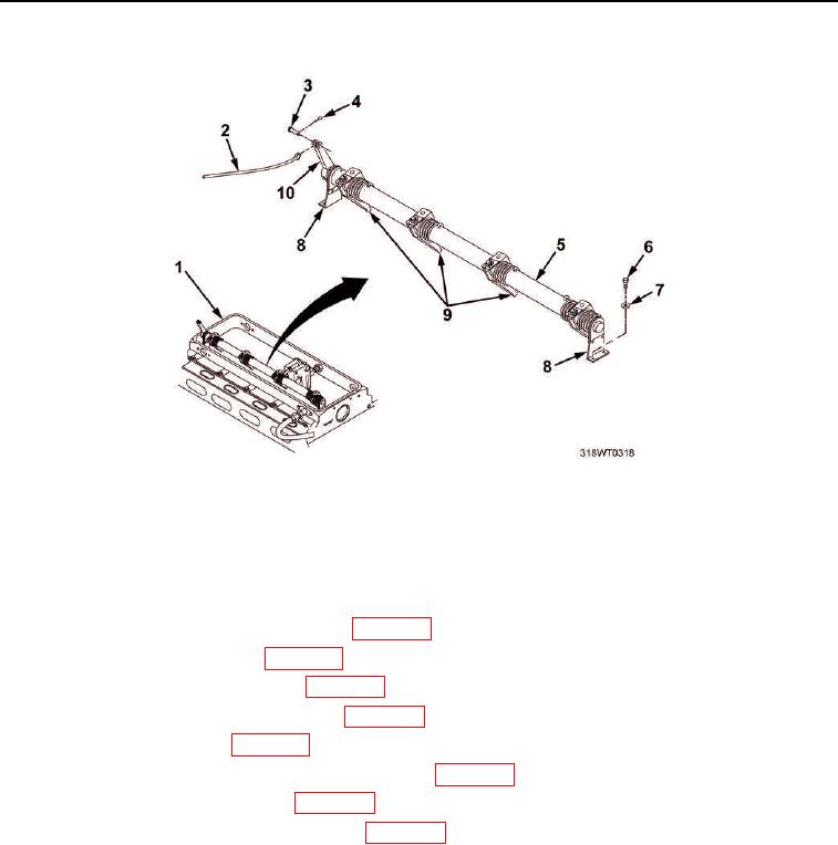
INSTALLATION - Continued
Figure 1. Fuel Injector Control Tube.
END OF TASK
FOLLOW-ON MAINTENANCE
1.
Check and adjust fuel modulator settings (WP 0090).
2.
Adjust the fuel injector timing (WP 0092).
3.
Install electronic governor actuator (WP 0098).
4.
Install electronic governor rod assembly (WP 0097).
5.
Install air intake housing (WP 0103).
6.
Install cylinder head poppet valve rocker arm covers (WP 0044).
7.
Install air inlet collector assembly (WP 0104).
8.
Install crankcase breather limiter assembly (WP 0106).
9.
Install engine hatch (TM 55-1925-205-23).
10.
Install operator's cab (TM 55-1925-205-10).
11.
Install intake plenum assembly (TM 55-1925-205-10).
12.
Install main navigation mast (TM 55-1925-205-10).
13.
Install SINCGARS antenna (TM 11-5820-890-10-8).
14.
Perform operational check of diesel engine (TM 55-1925-205-10).
END OF TASK
END OF WORK PACKAGE