
TM 55-2815-574-24
0101
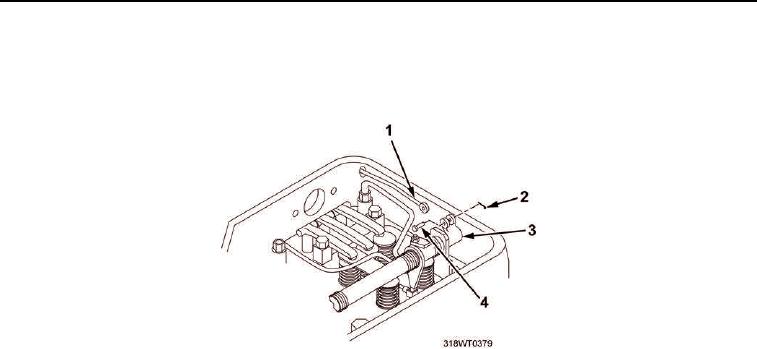
REMOVAL
1.
Remove cotter pins (Figure 1, Item 2) and clevis pins (Figure 1, Item 4) from fuel rods (Figure 1, Item 1) and
injector rack clevises (Figure 1, Item 3).
Figure 1. Injector Rack and Fuel Rods.
2.
Remove clamps (Figure 2, Item 5) from hoses (Figure 2, Item 6).
3.
Slide hoses (Figure 2, Item 6) up tubes (Figure 2, Item 1).
NOTE
Tag and retain bolts for proper installation.
4.
Remove seven cap screws (Figure 2, Item 8) and lockwashers (Figure 2, Item 7) from governor drive
(Figure 2, Item 4). Discard lockwashers.
5.
Remove three cap screws (Figure 2, Item 9) and copper washers (Figure 2, Item 10) from governor drive
(Figure 2, Item 4).
CAUTION
Do not pry governor drive from blower end plate, governor drive is doweled into position.
Failure to comply may result in damage to equipment.
6.
Tap governor drive (Figure 2, Item 4) with dead blow hammer to break seal from blower end plate
(Figure 2, Item 2).
7.
Remove governor drive (Figure 2, Item 4) from blower end plate (Figure 2, Item 2).
8.
Remove gasket (Figure 2, Item 3) from blower end plate (Figure 2, Item 2). Discard gasket.
END OF TASK
INSTALLATION
1.
Install new gasket (Figure 2, Item 3) on blower end plate (Figure 2, Item 2).
2.
Install governor drive (Figure 2, Item 4) on blower end plate (Figure 2, Item 2).
3.
Install three cap screws (Figure 2, Item 9) and copper washers (Figure 2, Item 10) on governor drive
(Figure 2, Item 4).
4.
Install seven cap screws (Figure 2, Item 8) and new lockwashers (Figure 2, Item 7) on governor drive
(Figure 2, Item 4).