
TM 55-2815-574-24
0114
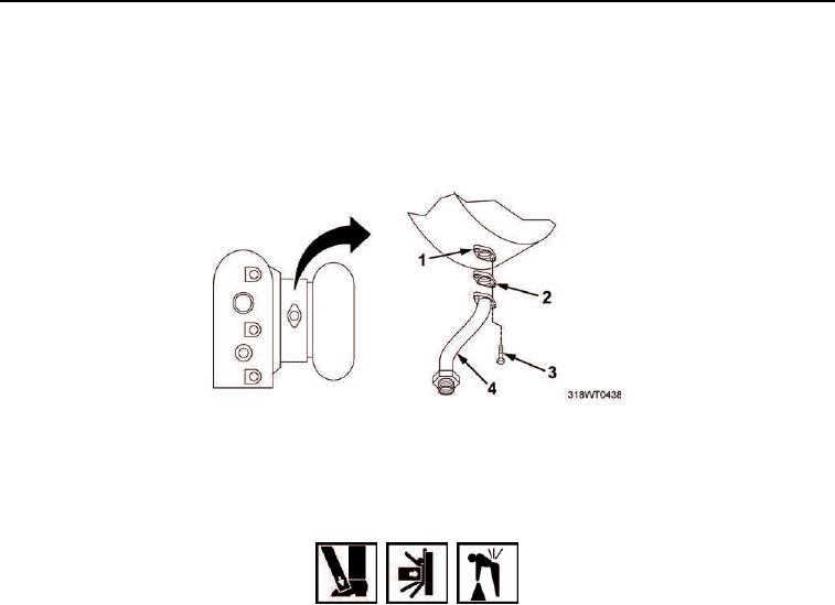
REMOVAL - Continued
12.
Remove two hex head bolts (Figure 4, Item 3) securing oil drain hose (Figure 4, Item 4) to turbocharger
(Figure 4, Item 1).
13.
Remove oil drain hose (Figure 4, Item 4) from turbocharger (Figure 4, Item 1).
14.
Remove oil drain hose gasket (Figure 4, Item 2) from turbocharger (Figure 4, Item 1). Discard gasket.
Figure 4. Oil Drain Hose Removal.
15.
Remove four hex nuts (Figure 5, Item 1) and washers (Figure 5, Item 2) from studs (Figure 5, Item 4).
WARNING
Handling heavily weighted objects can cause bodily injury. Do not lift materials or
equipment over 50 lb (23 kg) without using appropriate material handling equipment.
Ensure proper lifting techniques are followed when removing or installing heavy
components. Use assistant(s) and/or suitable lifting device when lifting heavy parts of
components. Failure to comply may result in personnel injury, death, and/or damage
to equipment.
16.
Remove turbocharger (Figure 5, Item 6) from exhaust flange (Figure 5, Item 3).