
TM 55-2815-574-24
0114
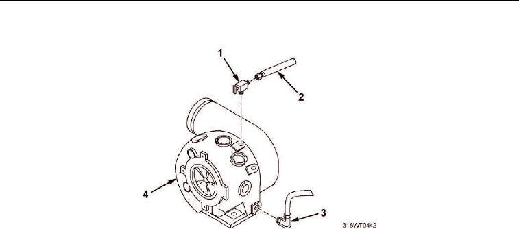
INSTALLATION - Continued
Figure 8. Coolant Lines Installation.
11.
Install new gasket (Figure 9, Item 11) on turbocharger (Figure 9, Item 1).
12.
Install exhaust elbow (Figure 9, Item 6) on turbocharger (Figure 9, Item 1).
13.
Install four cap screws (Figure 9, Item 5), washers (Figure 9, Item 4) and clamps (Figure 9, Item 3) securing
exhaust elbow (Figure 9, Item 6) to turbocharger (Figure 9, Item 1).
14.
Connect hose (Figure 9, Item 8) on exhaust elbow (Figure 9, Item 6).
15.
Install two clamps (Figure 9, Item 7) on hose (Figure 9, Item 8).
16.
Tighten clamps (Figure 9, Item 7).
17.
Install hose (Figure 9, Item 9) on side of exhaust elbow (Figure 9, Item 6).
18.
Install two clamps (Figure 9, Item 10) on hose (Figure 9, Item 9).
19.
Tighten hose clamps (Figure 9, Item 10).