
TM 55-2815-574-24
0119
NOTE
This task is typical for both port and starboard engines.
REMOVAL
NOTE
After removal of capscrews from oil pump assembly it may be necessary to strike sides of
oil pump assembly with soft mallet to free it from crankshaft assembly.
1.
Position drain pan under oil pump (Figure 1, Item 3).
2.
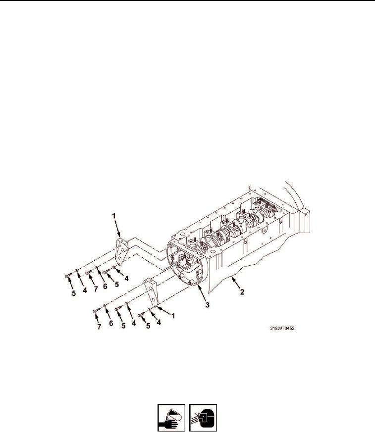
Remove two capscrews (Figure 1, Item 7) and lockwashers (Figure 1, Item 6) from engine mount brackets
(Figure 1, Item 1). Discard lockwashers.
3.
Remove four capscrews (Figure 1, Item 5) and lockwashers (Figure 1, Item 4) securing engine mount
brackets (Figure 1, Item 1) and oil pump (Figure 1, Item 3) to engine block (Figure 1, Item 2). Discard
lockwashers.
4.
Remove brackets (Figure 1, Item 1) from oil pump (Figure 1, Item 3).
Figure 1. Oil Pump Brackets.
5.
Remove 4 remaining capscrews (Figure 2, Items 3 and 5) and lockwashers (Figure 2, Items 2 and 4)
securing oil pump assembly (Figure 1, Item 3) to engine block (Figure 2, Item 1). Discard lockwashers.
WARNING
Fuel/Oil may cause irritation to eyes or skin. Wear protective goggles, gloves, and clothing.
Failure to comply may result in personnel injury or death.
6.
Remove oil pump assembly (Figure 1, Item 3) from engine block (Figure 1, Item 2).
7.
Remove oil pump gasket (Figure 2, Item 7) from engine block (Figure 2, Item 1). Discard gasket.