
TM 55-2815-574-24
0120
ASSEMBLY
1.
Apply a light coat of lubricating oil to pump gears.
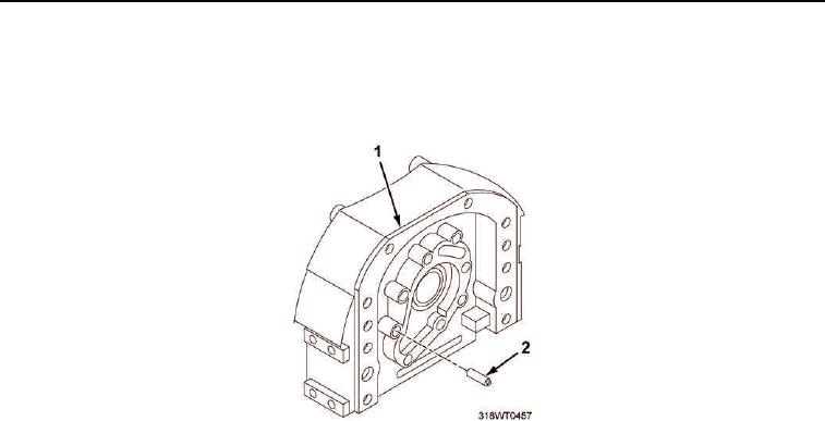
2.
Install shaft (Figure 3, Item 2) into front cover (Figure 3, Item 1).
Figure 3. Front Cover Assembly.
3.
Install drive gear (Figure 2, Item 2), hub (Figure 2, Item 3), and driven gear (Figure 2, Item 4) into front cover
(Figure 2, Item 1).
4.
Install retaining plate (Figure 1, Item 2) over gears and on front cover (Figure 1, Item 1).
NOTE
During following procedure self-locking bolts must be used due to close proximity of oil
pump and crankshaft.
5.
Install eight self-locking bolts (Figure 1, Item 3) into retaining plate (Figure 1, Item 2).
6.
Using torque wrench, torque bolts (Figure 1, Item 3) to 156 to 204 in-lb (18 to 23 Nm).
END OF TASK
END OF WORK PACKAGE