
TM 55-2815-574-24
0120
INSPECTION - Continued
6.
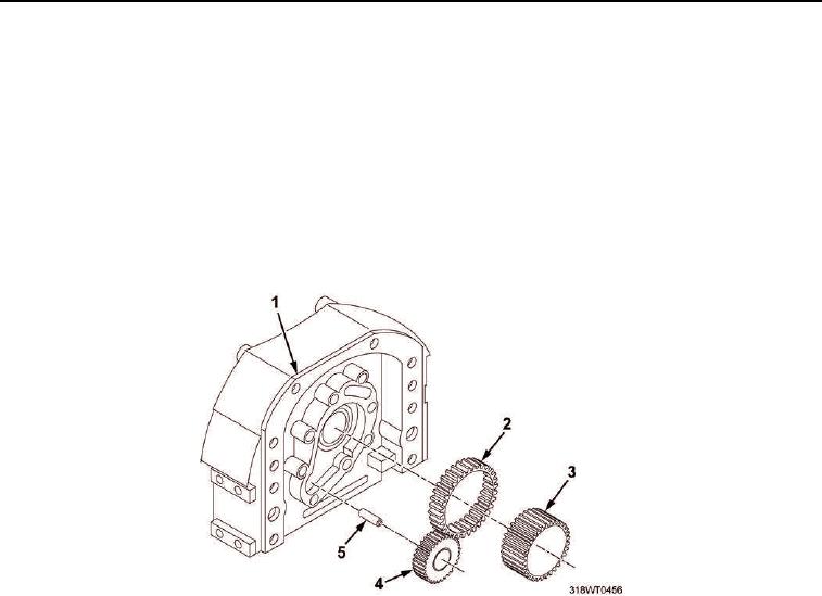
Inspect new driven gear and bushing (Figure 2, Item 4) to be used.
a.
Verify clearance between new driven gear and bushing (Figure 2, Item 4) and shaft (Figure 2, Item 5)
is within tolerance of 0.001 to 0.0025 in. (0.0254 to 0.0889 mm).
b.
Using micrometer, measure diameter of shaft (Figure 2, Item 5).
c.
Using inside micrometer, measure inside diameter of driven gear and bushing (Figure 2, Item 4).
d.
Subtract measurement obtained in Step b from measurement in Step c to obtain clearance specified in
Step a.
7.
Inspect inner face of retaining plate (Figure 1, Item 2) for damage, wear or scoring. Replace damaged parts.
Figure 2. Oil Pump Gears.
END OF TASK