
TM 55-2815-574-24
0121
INSPECTION - Continued
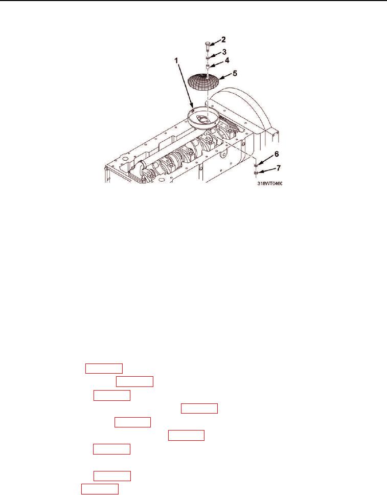
Figure 1. Oil Pump Inlet Screen.
END OF TASK
INSTALLATION
1.
Install screen (Figure 1, Item 5) into cover (Figure 1, Item 1).
2.
Install spacer (Figure 1, Item 4), washer (Figure 1, Item 3), and bolt (Figure 1, Item 2) into screen
(Figure 1, Item 5).
3.
Install washer (Figure 1, Item 6) and nut (Figure 1, Item 7) on bolt (Figure 1, Item 2).
4.
Tighten bolt (Figure 1, Item 2).
END OF TASK
FOLLOW-ON MAINTENANCE
1.
Install lube oil pan (WP 0127).
2.
Remove engine from stand (WP 0033).
3.
Install lube oil cooler (WP 0128).
4.
Install marine gear oil cooler mounting bracket (WP 0158).
5.
Install overspeed governor (WP 0169).
6.
Install lube oil level dipstick tube assembly (WP 0130).
7.
Install starting motor (WP 0164).
8.
Install air box drains (TM 55-1925-205-10).
9.
Install air box covers (WP 0036).
10.
Install fuel cooler (WP 0081).
11.
Install marine gear oil cooler (TM 55-2040-211-24).