
TM 55-2815-574-24
0122
REMOVAL
1.
Remove oil pump screen (Figure 1, Item 5) from tube assembly (Figure 1, Item 1) as follows:
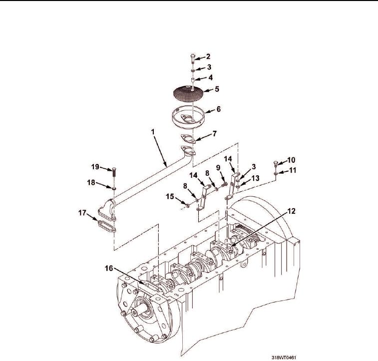
Figure 1. Lube Oil System Distribution Components.
a.
Remove two bolts (Figure 1, Item 2), four washers (Figure 1, Item 3), two spacers (Figure 1, Item 4),
and two nuts (Figure 1, Item 13) that secure oil pump screen (Figure 1, Item 5), cover
(Figure 1, Item 6), and gasket (Figure 1, Item 7) to tube assembly (Figure 1, Item 1).
b.
Remove oil pump screen (Figure 1, Item 5) and cover (Figure 1, Item 6), and discard gasket
(Figure 1, Item 7).
2.
Remove tube assembly (Figure 1, Item 1) from oil pump housing (Figure 1, Item 16) as follows:
a.
Remove two bolts (Figure 1, Item 19) and two lockwashers (Figure 1, Item 18) that secure tube
assembly (Figure 1, Item 1) to oil pump housing (Figure 1, Item 16). Discard lockwashers.
b.
Remove tube assembly (Figure 1, Item 1).