
TM 55-2815-574-24
0148
REMOVAL
1.
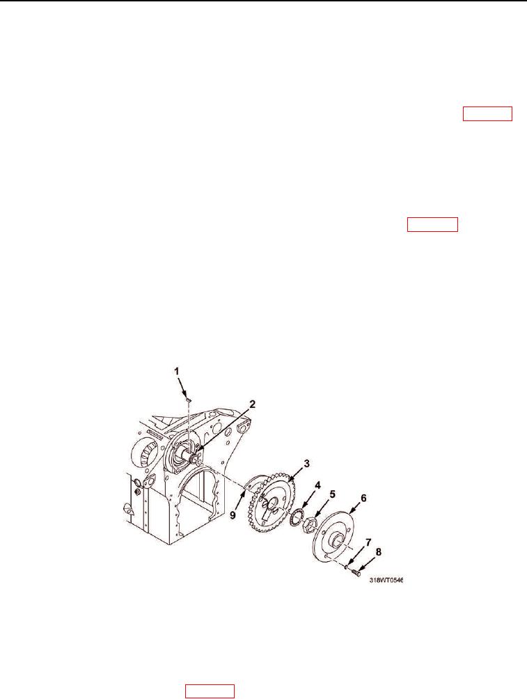
Remove three screws (Figure 1, Item 8), lockwashers (Figure 1, Item 7), and hub (Figure 1, Item 6) from
drive gear (Figure 1, Item 3). Discard lockwashers.
2.
Remove nut (Figure 1, Item 5), lockwasher (Figure 1, Item 4), and drive gear (Figure 1, Item 3) from shaft
(Figure 1, Item 2).
3.
Remove engine camshaft balance weight (Figure 1, Item 9) from drive gear (Figure 1, Item 3) (WP 0066).
4.
Remove woodruff key (Figure 1, Item 1) from shaft (Figure 1, Item 2). Discard woodruff key.
END OF TASK
INSTALLATION
1.
Install new woodruff key (Figure 1, Item 1) on shaft (Figure 1, Item 2).
2.
Install camshaft balance weight (Figure 1, Item 9) on drive gear (Figure 1, Item 3) (WP 0066).
3.
Apply thin film of grease to shaft (Figure 1, Item 2).
4.
Install new drive gear (Figure 1, Item 3) on shaft (Figure 1, Item 2).
5.
Hold drive gear (Figure 1, Item 3) in position and install lockwasher (Figure 1, Item 4) and nut
(Figure 1, Item 5) on shaft (Figure 1, Item 2).
6.
Using torque wrench and socket set, torque nut (Figure 1, Item 5) to 300 to 325 ft-lb (407 to 441 Nm).
7.
Align hub (Figure 1, Item 6) mounting holes with drive gear (Figure 1, Item 3) mounting holes.
8.
Install three new lockwashers (Figure 1, Item 7) and screws (Figure 1, Item 8). Tighten screws.
Figure 1. Fresh Water Cooling System Pump Drive Gear.
END OF TASK
FOLLOW-ON MAINTENANCE
1.
Install front balance weight cover (WP 0077).