
TM 55-2815-574-24
0166
REMOVAL - Continued
3.
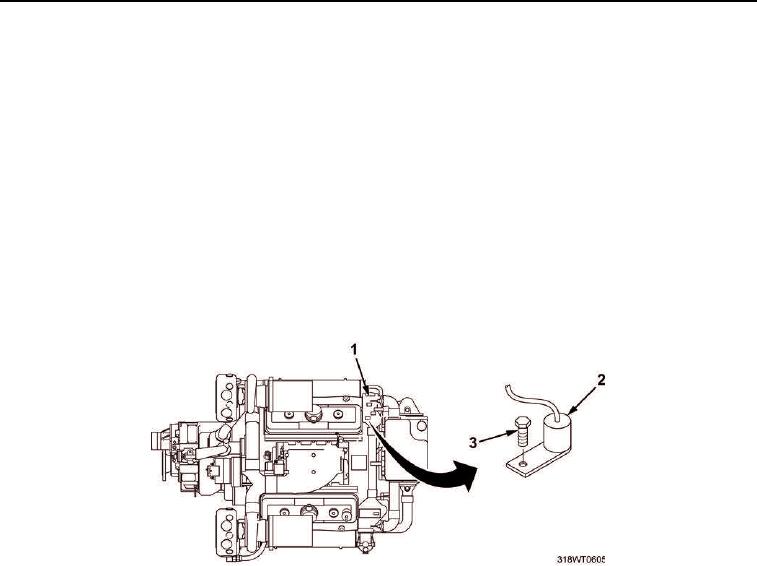
Tag and disconnect cold start temperature switch (Figure 2, Item 2) wire.
4.
Remove hex head bolt (Figure 2, Item 3) securing cold start temperature switch (Figure 2, Item 2) to
portside thermostat housing (Figure 2, Item 1).
5.
Remove cold start temperature switch (Figure 2, Item 2) and discard.
END OF TASK
INSTALLATION
1.
Position new cold start temperature switch (Figure 2, Item 2) on portside thermostat housing
(Figure 2, Item 1).
2.
Install hex head bolt (Figure 2, Item 3) to secure cold start temperature switch (Figure 2, Item 2) to the
portside thermostat housing (Figure 2, Item 1). Tighten hex head bolt (Figure 2, Item 3).
Figure 2. Cold Start Switch.
3.
Connect wire and remove tag.
4.
Remove LO/TO from A3 breaker switch. Refer to FM 4-01.502 for LO/TO procedure.
END OF TASK
FOLLOW-ON MAINTENANCE
Perform operational check of diesel engine (TM 55-1925-205-10).
END OF TASK
END OF WORK PACKAGE