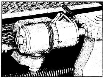
Figure 9-17.—Micrometer carriage stop.
the lead screw. On the upper end of the shaft is the dial.
As the lead screw revolves, the dial is turned and the
graduations on the dial indicate points at which the
half-nuts may be engaged.
Carriage Stop
The carriage stop can be attached to the bed at any
point where the carriage should stop. It is used primarily
for turning, facing, or boring duplicate parts, as it
eliminates taking repeated measurements of the same
dimension. In operation, the stop is set at the point where
the feed should stop. To use the stop, just before the
carriage reaches the stopping point, shut off the
automatic feed and manually run the carriage up against
the stop. Carriage stops are provided with or without
micrometer adjustment. Figure 9-17 shows a
micrometer carriage stop. Clamp it on the ways in the
approximate position required, and then adjust it to the
exact setting by using the micrometer adjustment. (Do
not confuse this stop with the automatic carriage stop
that automatically stops the carriage by disengaging the
feed or stopping the lathe.)
MAINTENANCE
Every lathe must be maintained strictly according
to requirements of the Maintenance and Material
Management (3-M) Systems. The first requirement of
maintenance to your lathe is proper lubrication. Make it
a point to oil your lathe daily where oil holes are
provided. Oil the ways daily-not only for lubrication but
to protect their scraped surfaces. Oil the lead screw often
while it is in use; this is necessary to preserve its
accuracy, for a worn lead screw lacks precision in thread
cutting. Make sure the headstock is filled to the proper
oil level; drain the oil out and replace it when it becomes
dirty or gummy. If your lathe is equipped with an
automatic oiling system for some parts, make sure all
those parts are getting oil. Make it a habit to CHECK
frequently to see that all moving parts are being
lubricated.
Before engaging the longitudinal ‘feed, be certain
that the carriage clamp screw is loose and that the
carriage can be moved by hand. Avoid running the
carriage against the headstock or tailstock while it is
under the power feed; running the carriage against the
headstock or tailstock puts an unnecessary strain on the
lathe and may jam the gears.
Do not neglect the motor just because it may be out
of sight; check its lubrication. If it does not run properly,
notify the Electrician’s Mate who is responsible for
caring for it. He or she will cooperate with you to keep
it in good condition. On lathes with a belt driven from
the motor, avoid getting oil or grease on the belt when
you oil the lathe or motor.
Keep your lathe clean. A clean and orderly machine
is an indication of a good mechanic. Dirt and chips on
the ways, on the lead screw, and on the crossfeed screws
will cause serious wear and impair the accuracy of the
machine.
NEVER put wrenches, files, or other tools on the
ways. If you must keep tools on the bed, use a board to
protect the finished surfaces of the ways.
NEVER use the bed or carriage as an anvil.
Remember, the lathe is a precision machine, and nothing
must be allowed to destroy its accuracy.
BASIC SETUP
A knowledge of the basic setup is required if you
are to become proficient in performing machine work
with a lathe. Some of these setups are considered in the
following sections.
Cutting Speeds and Feeds
Cutting speed is the rate at which the surface of the
work passes the point of the cutting tool. It is expressed
in feet per minute (fpm).
Feed is the amount the tool advances for each
revolution of the work. It is usually expressed in
thousandths of an inch per revolution of the spindle.
Cutting speeds and tool feeds are determined by
various considerations: the hardness and toughness of
9-10