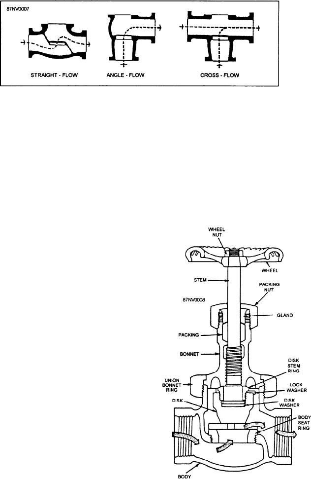
Figure 15-7.--Types of globe valve bodies.
Globe valve inlet and outlet openings are arranged
valve. Since regulating the flow of liquid would be
in several ways to satisfy different requirements of flow.
difficult and could cause extensive damage to the valve,
Figure 15-7 shows three common types of globe valve
the gate valve is not to be used as a throttling valve.
bodies. In the straight type, the fluid inlet and outlet
The gate is connected to the valve stem. Turning
openings are in line with each other. In the angle type,
the handwheel will raise or lower the valve gate. Some
the inlet and outlet openings are at an angle to each
gate valves have nonrising stems. On these, the stem is
other. An angle-type globe valve is commonly used
threaded on the lower end and the gate is threaded on
where a stop valve is needed at a 90 turn in a line. The
the inside. Therefore, the gate will travel up the stem
cross-type globe valve has three openings rather than
when the valve is being opened. This type of valve will
two; it is frequently used in connection with bypass
lines.
Globe valves are commonly used in steam, air, oil,
and water lines. On many ships, you will find surface
blow valves, bottom blow valves, boiler stops, feed stop
valves, and many guarding valves and line cutout
suction side of many fireroom pumps, as recirculating
valves in the fuel oil system, and as throttle valves on
most fireroom auxiliary machinery.
A cutaway view of a globe stop valve is shown in
figure 15-8.
GATE VALVES
Gate valves are used in systems where a straight
flow with the least amount of restriction is needed.
Figure 15-9 is a cross-sectional view of a gate valve.
You will find that most of the firemain cutout valves are
gate valves. These valves are also used in steam lines,
water lines, and fuel oil lines.
The part of a gate valve that serves the same purpose
as the disk in a globe valve is known as the gate. The
gate is normally wedge-shaped. However, some are
uniform in thickness throughout. When the gate is wide
open, the opening through the valve is equal to the size
of the piping in which the valve is installed. Therefore,
there is very little resistance in the flow of the liquid and
also very little pressure reduction caused by the gate
Figure 15-8.--Cutaway view of a globe stop valve.
15-10


