the slightest drop in delivered pressure, the pressure
charge in the dome instantly forces the valve open. This
allows system fluid to pass through, thereby
maintaining the outlet pressure relatively constant.
To charge the loading chamber, back off slightly on
the dome needle valve. Connect the specially furnished
hand pump (either 300 or 600 psi), and fill the dome to
the desired outlet pressure. If the regulator is to handle
a gas, charge the dome loading chamber with this gas
via the dome needle valve and the body needle valve
(fig. 15-15). If the regulator is to handle a liquid, charge
the dome from an external source. Remove the plug on
the dome loading chamber and connect the external
source. This may be an air bottle or an air pump. Keep
the body needle valve closed while you use the dome
needle valve to adjust the dome pressure to obtain the
desired outlet pressure.
HYDRAULIC CONTROL VALVES
Hydraulic control valves are used in many
shipboard systems. On some ships, they are installed in
the sections of firemain that supply water to the
magazine sprinkling systems. This type of valve may
be operated from one or more remote control stations
by a hydraulic control system.
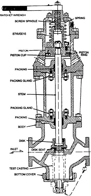
The hydraulic control valve shown in figure 15-16
is a piston-operated globe valve. It is normally held in
the closed position by both a spring force and by the
firemain pressure acting against the disk. When
hydraulic pressure is admitted to the underside of the
piston, a force is created that overcomes both the spring
tension and the firemain pressure, thereby causing the
valve to open.
Figure 15-16.--Hydraulic control valve.
When hydraulic pressure is released from under the
piston, the spring acts to force the hydraulic fluid out of
the cylinder and back to the remote control station, thus
can be removed so that you can check the valve for
closing the valve.
leakage.
A ratchet lever is fitted to the valve to allow the
emergency opening of the valve by hand. After the
TRAPS AND STRAINERS
valve has been opened by hand, you should first restore
Traps are used to remove various undesirable
the stem to its normal CLOSED position with the
materials from piping systems. In air lines, a trap is
ratchet lever. Then line up the hydraulic system from a
installed to remove the water that is usually present. In
remote control station so that the hydraulic fluid in the
steam lines, traps are installed to remove condensate.
valve cylinder can return to the storage tank at the
Some types of steam traps are suitable for low-pressure
control station. The full force of the closing spring then
use, while others are suitable for high-pressure use.
acts to seat the disk, thereby closing the valve.
However, any steam trap will consist of a valve and
The valve shown in figure 15-16 is equipped with
some device or arrangement that will cause the valve to
a test casting in the body of the valve. The bottom cover
open and close, as necessary to drain the condensate
from the lines without allowing steam to escape. The
15-15

