7. After you have tightened the mounting bolts,
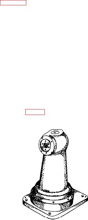
RIGHT-ANGLE MILLING ATTACHMENT
rotate the feed adjusting arm on the backing
plate until the arm points directly toward the
The right-angle milling attachment is mounted
front.
over the spindle sleeve and bolted directly to the face
of the head. It is driven by a drive dog inserted
8. Mount the restraining block on the head.
between the attachment and the spindle sleeve. This
attachment lets you perform milling operations at any
9. Set the slide manually; insert the tee-handled
angle setting through a full 360. You can perform
wrench into the slot in the slide adjusting dial
boring operations at right angles to the spindle axis
and turn the wrench until the slide is posi-
using either the head or the table feed depending on
tioned. The dial is graduated in thousandths of
the position of the hole to be bored. You may use
an inch and one complete turn equals a
standard milling machine tooling held in the spindle
0.125-inch movement of the slide.
by a drawbolt that extends through the spindle.
After the slide is clamped in place, a spring-
loaded safety clutch prevents movement of the slide
or damage to the feed mechanism if the feed is
BORING MILL OPERATIONS
inadvertently engaged. This is not provided to allow
continuous operation of the head when the slide is
clamped and the feed is engaged--it is a jamming
protection only. A distinct and continuous ratcheting
and boring operations. You also can use it to face
of the safety clutch warns you to unlock the slide or to
valve flanges, and bore split bearings and pump
disengage the feed. Do not confuse this warning with
cylindrical liners. We will explain these in the next
the intermittent ratcheting of the feed driving clutches
paragraphs.
as the head rotates. The same safety clutch stops the
feed at the end of travel of the slide that prevents
jamming of the slide or the mechanism through
Drilling, Reaming, and Boring
overtravel.
The slide directional lever is located on the
same way with both a horizontal boring mill and a
backing plate beneath the feed adjusting arm. The
radial drill. The major difference is the way the tool is
arrows on the face of the selector show which way it
held in the machine. It's horizontal in the horizontal
should be turned to feed the slide in either direction.
boring mill (fig. 8-11) and vertical in the radial drill.
There are also two positions of the selector to
disengage the slide feed. The direction of the spindle
rotation has no effect on the direction of the slide
feed.
The slide feed rate adjusting arm scale is
graduated in 0.010-inch increments from 0.000 to
0.050 inch, but the first two increments are each 0.005
inch. Set the feed rate by turning the knurled
adjusting arm to the desired feed in thousandths per
revolution.
When you mount the single-point toolholders, be
sure the tool point is on center or slightly below center
so the cutting edge has proper clearance at the small
diameters. You may damage the feed mechanism if
you operate the head with the tool above center.
After you mount the facing head, perform the
machining operation using the instructions in the
Figure 8-10.--Angular milling head.
operator's manual for your boring machine.
8-8


