The reference to the size of horizontal boring
1. Retract the spindle of the machine into the
mills differs with the manufacturer. Some use spindle
sleeve. Engage the spindle ram clamp lever.
size. For example, Giddings and Lewis model 300T
2. Disengage the overrunning spindle feed clutch
has a 3-inch spindle. Others use the largest boring bar
to prevent accidental engagement of the
the machine will accept. In planning a job, consider
spindle power feed while you mount the
both of these factors along with the table size and the
combination head on the machine. If the slide
height the spindle can be raised. Always refer to the
is centered and locked, you may run the
technical manual for your machine.
spindle through it for use in other operations
without removing the attachment, but be sure
It is most important that you set up the work
you disengage the spindle overrunning clutch
correctly. Mistakes cost man-hours and material.
Often you will find it's better to set up a casting to the
again before you resume use of the slide.
layout lines than to a rough surface since the layout
3. Set the spindle for the speed to be used.
lines will always be used as a reference.
4. When the combination head is mounted on the
Be sure the holding clamps used to secure a piece
sleeve, follow these steps: Before you shift
of work are tight. If you use braces, place them so
the spindle back-gear to neutral, or make any
they can't come loose. Fasten blocks, stops, and
spindle back-gear change, rotate the sleeve by
shims securely. If a workpiece is not properly
jogging it until the heavy end of the head is
secured, you could ruin the material or the machine
down. Any spindle back-gear change requires
and injure personnel.
a momentary shift to neutral which allows the
sleeve to turn freely. The sleeve may rotate
Different jobs may require different types of
unexpectedly until the heavy end of the facing
attachments. These attachments include angular
head is down, hitting you or the work.
milling heads, combination boring and facing heads,
thread lead arrangements, and so forth. Boring heads
5. Lift the head into position on the machine at
are available in a variety of diameters. These boring
the sleeve by inserting an eyebolt into the
heads are particularly useful to bore large diameter
tapped hole in the top of the head.
holes and face large castings. You also can use locally
made collars, and you can use stub arbors to increase
6. To line up the bolt holes in the sleeve with
diameters.
those in the head, jog the spindle into position.
COMBINATION BORING AND FACING
HEAD
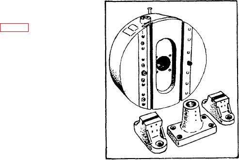
face and bore large diameters. It is mounted and
bolted directly to the spindle sleeve, and it has a slide
with automatic feed that holds the boring or facing
tools. (This attachment can be fed automatically or
positioned manually.) There are various sizes, but
each is made and used similarly. The heads are
balanced to permit high-speed operation with the tool
slide centered. Whenever you use tools off center, be
sure you counterbalance the head, or use it at lower
speeds.
Generally, the boring and facing head will come
equipped with several toolholders for single-point
tools, a right-angle arm, a boring bar, and a boring bar
holder that mounts on the slide. Use the following
instructions to set up and operate the boring and
Figure 8-9.--Combination boring and facing head.
facing head:
8-7


