TM 55-2815-574-24
0003
COOLING SYSTEM - Continued
Heat Exchanger
The heat exchanger core consists of a series of cells with a header at one end and a circular water outlet at the
opposite end. The core is mounted inside of the expansion tank with the header or inlet end bolted to the tank and
the opposite or outlet end is sealed inside a retainer. A gasket between the expansion tank and the flange of the
core, another gasket between the flange of the core and the cover at the inlet side, and seals surrounding the
circular outlet at the opposite end prevent the coolant from mixing with the raw cooling water on its horizontal
course between the cells of the element. In this system of engine cooling, the hot coolant leaving the thermostat
housing passes through the expansion tank, then through the cells of the cooling core. After leaving the heat
exchanger, the engine coolant is picked up by the fresh water pump and circulated through the cylinder block and
cylinder heads. The raw water is forced horizontally between the cells of the core and serves to lower the
temperature of the coolant as it passes through the cells. To protect the heat exchanger core from electrolytic
action of the raw water, a zinc electrode is located in both the heat exchanger inlet elbow and the raw water pump
inlet elbow and extends into the raw water passage. The expansion tank provides a means of filling the engine
cooling system, as well as space for expansion of the coolant as its temperature rises. An overflow pipe, near the
top of the tank, provides a vent to the atmosphere. The length of time a heat exchanger will function satisfactorily
before cleaning will be governed largely by the kind of coolant used in the engine and the kind of raw water used.
Soft water, plus a good commercial rust inhibitor or antifreeze should be used as the engine coolant to prevent
lime deposits in the heat exchanger core as well as in the engine. Enough coolant should be maintained in the
engine to fill the cylinder block and head, and to partially fill the water tank. Allow air space above the coolant in
the tank for the increase in volume as the temperature of the coolant rises. Whenever the heat exchanger fails to
cool the engine properly, and the raw water pump is circulating a normal amount of cooling water around the heat
exchanger core, the core should be examined for foreign deposits.
Raw Water Pump
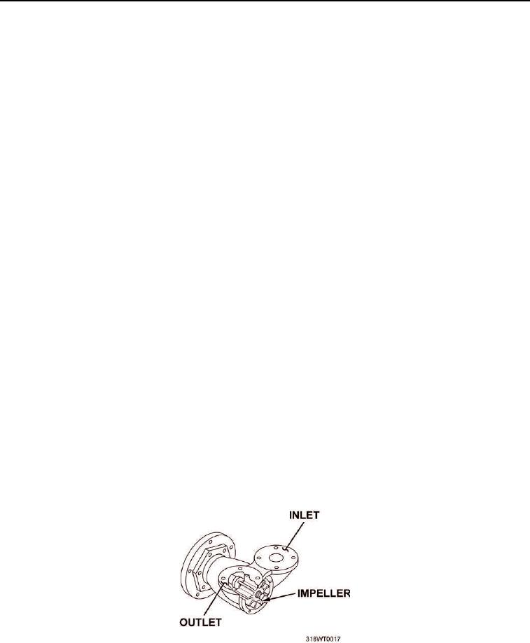
Raw water for lowering the temperature of the engine coolant is circulated through the heat exchanger by a
positive displacement pump. The pump is attached to an adapter which, in turn, is bolted to the flywheel housing
and is driven through a coupling attached to the left-hand camshaft gear. The pump driveshaft is supported by a
prelubricated, shielded double-row ball bearing. An oil seal prevents oil leakage from the bearing compartment
and a rotary type seal prevents water leakage along the shaft. An impeller, splined to the end of the driveshaft, is
self-lubricated by the water pumped and should not be run dry for longer than normally required for the pump to
prime itself. A wear plate in the impeller compartment prevents wear of the pump housing and can be reversed if
wear on the plate becomes excessive. A slot machined in the outer periphery of the wear plate mates with a
dowel in the pump housing, thus preventing it from rotating with the shaft. The pump can be operated in a
clockwise or counterclockwise direction. Raw water is drawn into the pump through an inlet opening and
discharged through the outlet opening, both openings are located at the top of the pump housing.
Figure 9. Raw Water Pump.

