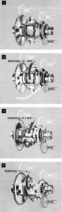
Figure 11-11.—How a differential works.
Now let’s look at figure 11-11. In this hookup the
two end gears are positioned by the input shafts,
which represent the quantities to be added or
subtracted. The spider gears do the actual adding and
subtracting. They follow the rotation of the two end
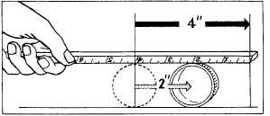
Figure 11-12.—The spider makes only half as many
revolutions.
gears, turning the spider shaft several revolutions
proportional to the sum, or difference, of the
revolutions of the end gears.
Suppose the left side of the differential rotates
while the other remains stationary, as in block 2 of
figure 11-11. The moving end gear will drive the
spider in the same direction as the input and,
through the spider shaft and output gear, the output
shaft. The output shaft will turn several revolutions
proportional to the input.
If the right side is not rotated and the left side is
held stationary, as in block 3 of figure 11-11, the
same thing will happen. If both input sides of the
differential turn in the same direction at the same
time, the spider will be turned by both at once, as in
block 4 of figure 11-11. The output will be
proportional to the two inputs. Actually, the spider
makes only half as many revolutions as the
revolutions of the end gears, because the spider gears
are free to roll between the end gears. To understand
this better, let’s look at figure 11-12. Here a ruler is
rolled across the upper side of a cylindrical drinking
glass, pushing the glass along a table top. The glass
will roll only half as far as the ruler travels. The
spider gears in the differential roll against the end
gears in exactly the same way. Of course, you can
correct the way the gears work by using a 2:1 gear
ratio between the gear on the spider shaft and the
gear for the output shaft. Very often, for design
purposes, this gear ratio will be found to be different.
When two sides of the differential move in
opposite directions, the output of the spider shaft is
proportional to the difference of the revolutions of the
two inputs. That is because the spider gears are free
to turn and the two inputs drive them in opposite
directions. If the two inputs are equal and opposite,
the spider gears will turn, but the spider shaft will
not move. If the two inputs turn in opposite directions
for an unequal number of revolutions, the spider
gears roll on the end gear that makes the lesser
number of revolutions. That rotates the spider in the
direction of the input making the greater number of
revolution. The motion of the spider shaft
11-8