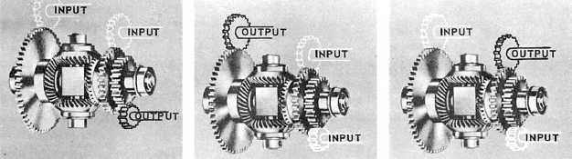
Figure 11-13.—Differential gear hookups.
will be equal to half the difference between the
revolutions of the two inputs. A change in the gear
ratio to the output shaft can then give us any
proportional answer we wish.
We have been describing a hookup wherein the
two sides are inputs and the spider shaft is the
output. As long as you recognize that the spider
follows the end gears for half the sum, or
difference, of their revolutions, you don’t need to
use this type of hookup. You may use the spider
shaft as one input and either of the sides as the
other. The other side will then become the output.
Therefore, you may use three different hookups
for any given differential, depending on which is
the most convenient mechanically, as shown in
figure 11-13.
In chapter 13 of this book, we will describe the
use of the differential gear in the automobile.
Although this differential is similar in principle,
you will see that it is somewhat different in its
mechanical makeup.
LINKAGES
A linkage may consist of either one or a
combination of the following basic parts:
1. Rod, shaft, or plunger
2. Lever
3. Rocker arm
4. Bell crank
These parts combined will transmit limited
rotary or linear motion. To change the direction of
a motion, we use cams with the linkage.
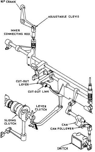
Lever-type linkages (fig. 11-14) are used in
equipment that you open and close; for instance,
valves in electric-hydraulic systems, gates
clutches, and clutch-solenoid interlocks. Rocker
arms are merely a variation, or special use, of
levers.
Bell cranks primarily transmit motion from
a link traveling in one direction to
another link moving in a different direction.
The bell crank mounts on a fixed
Figure 11-14.—Linkages.
11-9