--Select the appropriate die, depending on the
--Make no modifications that will speed up or
punch-to-die clearance. Figure 13-26 shows the
continually cycle machine.
punch-to-die clearance. The punch-to-die clearance is
PUNCHING OPERATIONS.--The punch end of
the distance between the outer circumference of the
the universal ironworker punches rounds, squares, and
punch and the inner circumference of the die, when the
oblongs. The deep punch throat allows punching to the
punch sits in the die.
center of wide plates. The standard universal die block
--The punch diameter must be the same thickness
permits punching a full range of angles, beams, and
or greater than the plate thickness being punched.
channels.
--The punch-to-die clearance for mild steel with a
Punch Head.--The main part of the punching
thickness of l/4 inch through 5/8 inch should be l/32
device is a punch head. In the older machines, the
inch.
punch head is referred to as a full-floating head since
the dieblock is adjustable to allow the alignment of the
--The punch-to-die clearance for 3/4-inch mild
die to the punch. In the newer machines, the dieblock
steel should be l/16 inch.
is stationary while the die is adjusted for alignment with
--For metal less than l/4 inch, the recommended
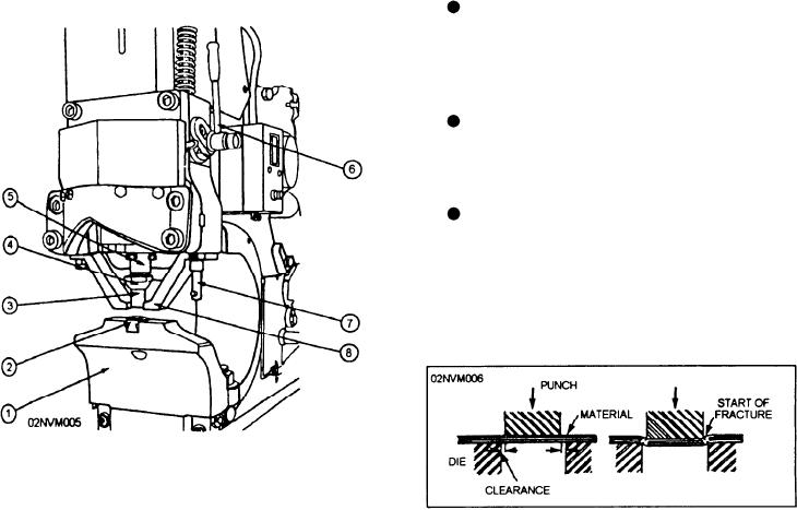
the punch. The major components of the punch end are
punch-to-die clearance is l/10 of the thickness of the
as follows (fig. 13-25).
material.
Punch and Die Selection.--On the punch end, the
--The punch-to-die ratio should never be less than
punch to die selection is the utmost importance. Select
0.010 inch due to working clearances necessary in the
the proper size and shape of the punch and die according
punch head.
to the type and thickness of material to be punched.
Operating Procedure. --To operate the punch,
Refer to the manufacturer's manual for standard tooling
refer to figure 13-25 and proceed according to the
sizes. You should keep the following points in mind
following precautions and steps:
when selecting punches and dies.
Install the punch and die and check the
alignment and adjust as necessary. Ensure that
the punch passes through the die without
striking the shoulders of the die.
Cycle the machine through one complete
revolution checking the machine for binding or
misalignment.
Place the workpiece under the punch and
"spot" the punch to the workpiece. This may
be accomplished by using the hand lever in the
older mechanical machines or by the jog button
on the hydraulic machines.
1.
Dieblock
5.
Punch Holder
6.
Hand Lever
2.
Die
7.
Stripper ACS Lever
3.
Punch
8.
Stripper
4.
Coupling Nut
Figure 13-26.--Punch-to-die clearance.
Figure 13-25.--Punch floating head.
13-24

