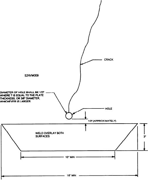
Figure 13-55.--Ductile metal overlay to arrest cracks in surface ship hull structure.
Flame shrinkage can also be used to give a beam a
the development of locked-in stresses. When you use
desired amount of curvature. Figure 13-59 shows a
the flame shrinkage process, be sure you proceed
rolled beam with a cover plate welded to the lower
cautiously, periodically allowing cooling to take place,
flange. The bend resulting from the welding on the
and checking on the degree of distortion (buckling)
cover plate has not produced enough curvature and it is
removed.
decided to use flame shrinkage to get the desired
amount. How is this to be done?
A beam with a cover plate welded to it (fig. 13-58)
is very likely to bend in the direction of the cover plate
If the cover plate alone is heated and shrunk, it will
pull against the lower beam flange and you will get a
because the welding is not balanced about the neutral
considerable amount of locked-in tensile stress. Should
axis. Essentially, the act of welding on the cover plate
the beam at some later time be accidentally overloaded,
produces shrinkage that shortens the length of the flange
the yield point of the cover plate might be exceeded.
to which it is welded, as shown in view B of figure
This will cause stretching and some of the curvature will
13-58. You should then use flame shrinkage to shorten
be lost. It would be desirable to minimize the tension
the other flange to the same length, thus straightening
stress developed in the cover plate by flame shrinkage
so that a larger amount of the strength may be used to
the beam as shown in view C of figure 13-58.
13-50

