
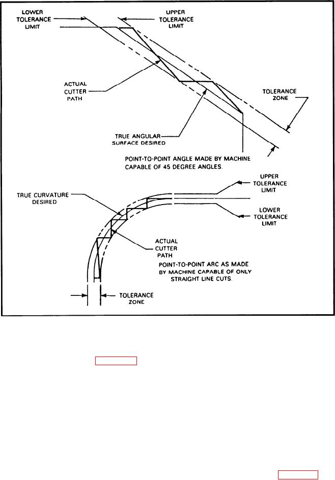
Figure 11-7.--Point-to-point angles and arcs.
Point-to-point machines move only in straight
manufactured by the same company. Figure 11-6 shows
lines. They are limited in a practical sense to hole
a typical controller. Each controller is manufactured
with a standard set of built-in codes. Other codes are
straight milling cuts parallel to a machine axis. When
added by the machine tool builders. For this reason,
making an axis move, all affected drive motors run at
program codes differ somewhat from machine to
the same speed. When one axis motor has moved the
machine. Every CNC machine, regardless of manu-
instructed amount, it stops while the other motor
facture, is a collection of systems coordinated by the
continues until its axis has reached its programmed
controller.
location. This makes the cutting of 45-degree angles
possible, but not arcs or angles other than 45 degrees.
TYPES OF CONTROL SYSTEMS
Arcs and angles must be programmed as a series of
straight line cuts, as shown in figure 11-7.
There are two types of control systems used on NC
A continuous-path machine can move its drive
machines: point-to-point systems and continuous-path
motors at varying rates of speed while positioning the
systems.
machine. Therefore, it can more easily cut arcs and
11-7