6. Find the NPD.
7. Find the
8. Find the RPC.
9. Find the lead.
10. Find the change gear.
11. Find the NTCS.
12. Make sure the cutter has the correct DP and
cutter number.
13. Find your corrected chordal addendum and
chordal thickness.
14. Find your corrected whole depth (WD).
15. Determine what kind of material the sample
gear is to be made of.
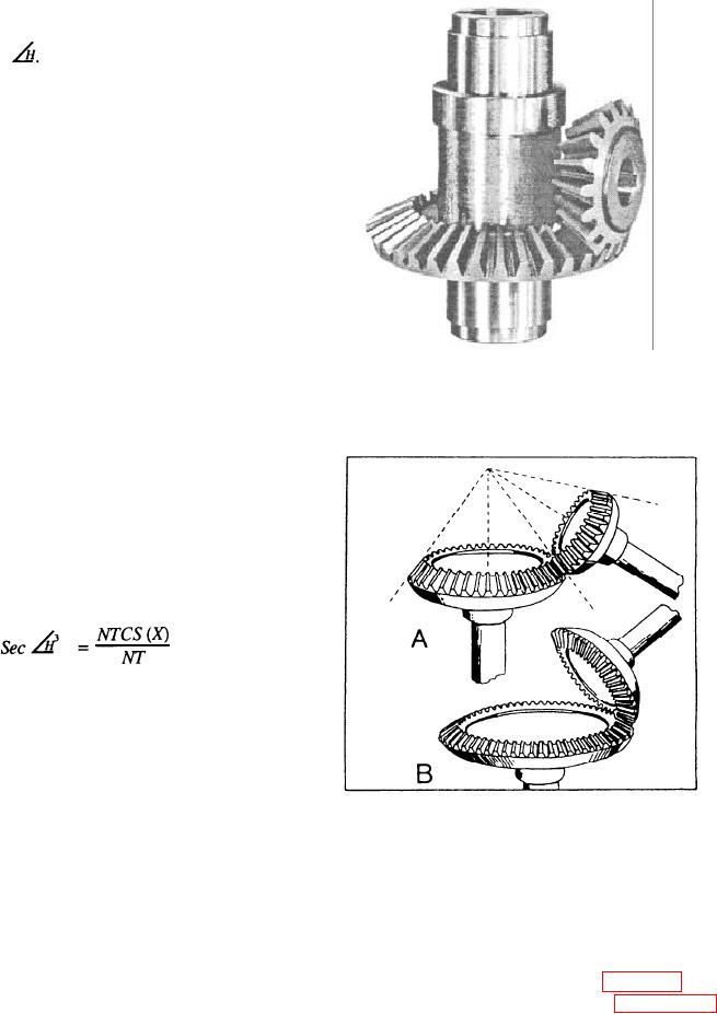
Figure 14-12.--Bevel gear and pinion.
Now you are ready to machine your gear.
Use the following hints to manufacture a helical
gear:
1. Make all necessary calculations that are needed
to compute the dimensions of the gear.
2. Set up the milling machine attachments for
machining.
3. Select and mount a gear cutter. Use the formula
4. Swivel the milling machine table to the helix
angle for a right-hand helix; face the machine
and push the milling machine table with your
right hand. For a left-hand helix, push the table
with your left hand.
5. Set the milling machine for the proper feeds
A. With shafts less than 90 apart
and speeds.
B. With shafts more than 90 apart
6. Mount the change gears. Use the gear train
Figure 14-13.--Other forms of bevel gears.
ratio formula to determine your change gears.
7. Mount the gear blank for machining.
BEVEL GEARS
8. Set up the indexing head for the correct number
of divisions.
Bevel gears have a conical shape (fig. 14-12) and
are used to connect intersecting shafts. Figure 14-13,
9. Before cutting the teeth to the proper depth,
view A, shows an example of bevel gears with shafts
double check the setup, the alignment, and all
set at less than 90. View B shows those set at more than
calculations.
90. There are several kinds of bevel gear designs. We
10. Now you are ready to cut your gear.
will discuss the straight-tooth design because it is the
most commonly used type in the Navy. The teeth are
11. Remove and deburr the gear.
14-14

